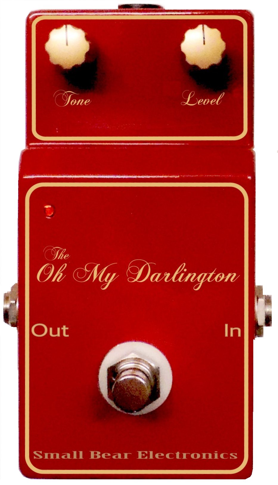
The Oh My Darling(ton)
A "'60s Convertible" Rangemaster
© 2012 By Small Bear Electronics LLC
 Here
is my first "build-it-this-way" tutorial using my Bare Box #1
construction platform. The Oh My Darling Rangemaster incorporates a number of
Bearishly-clever construction techniques and technical tweaks that make it
unusually fun-to-build and useful.
Here
is my first "build-it-this-way" tutorial using my Bare Box #1
construction platform. The Oh My Darling Rangemaster incorporates a number of
Bearishly-clever construction techniques and technical tweaks that make it
unusually fun-to-build and useful.
This article describes a perfboard version and includes technical detail
meant for intermediate-to-advanced hobbyists. For those who want an easier
build, a kit with a ready-to-solder PC board is available. The instruction
manual files (which include numerous high-resolution photos) can be found
here:
Whether on perf or PCB, the build can be configured with jumpers to be:
- A "standard" one-transistor RM
- The two-NPN transistor Oh My Darling
- A hybrid NPN-PNP Sziklai Darlington boost
Because the
devices are NPN, no separate power supply is needed when setting up the pedal
on a board. Better yet, the darlington versions produce perfect Rangemaster
biasing and tone using transistors that used to be considered discards. Here is a look at the
two-NPN circuit:
Cascading two relatively low-gain devices to get a "composite" higher-gain
part was fairly common back when making single high-gain germanium parts was
much more difficult. My implementation plays into the present transistor
market, in which there is a lot of inexpensive low-gain/low-leakage NPN
germanium sitting unused because "everyone knows that you need a minimum gain
of 70 to get the biasing right." By selecting the transistors and adjusting Rc and Rd, you can make the
effective gain of the pair whatever you need it to be within very broad
limits. Low-gain parts are usually also low-leakage, so temp stability is
reasonable. Tone? I will gladly stack up one of my builds against any
one-device, "boutique" Rangemaster clone. The Oh My Darling is all-gain/no-pain, and it
can be built with a wide variety of inexpensive parts, both silicon and
germanium.
The Hungarian engineer who came up with complementary configurations gave
his name to the Sziklai darlington pair. Here is the NPN version, with the appropriate bias
resistors to create an "Oh My Sziklai" or "Really Szik" Rangemaster. "Szik" in
a good way, of course!:

As you can see, the hybrid Q1-Q2 gain block easily drops into the same circuit
position as the regular darlington. Its Q2 position offers a great way to make
use of your drawer-full of 2N404s that were not hot enough to use in Tone Benders.
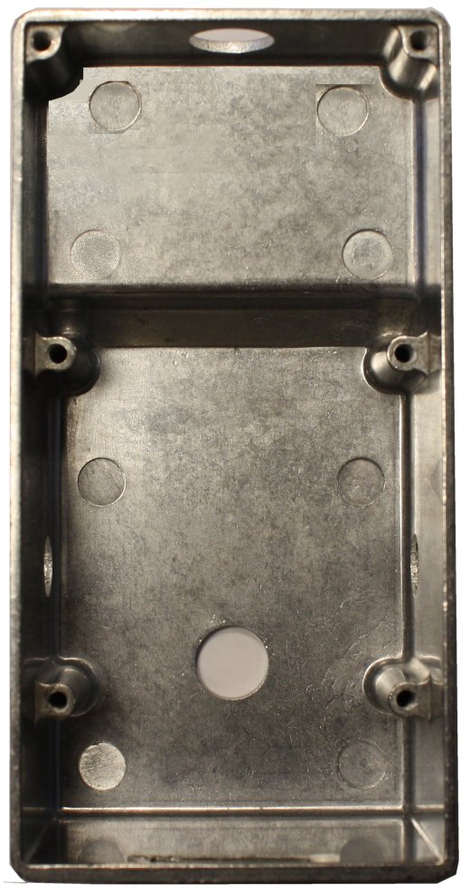
How To Build One
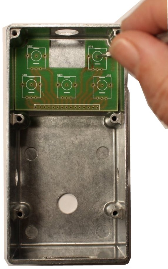
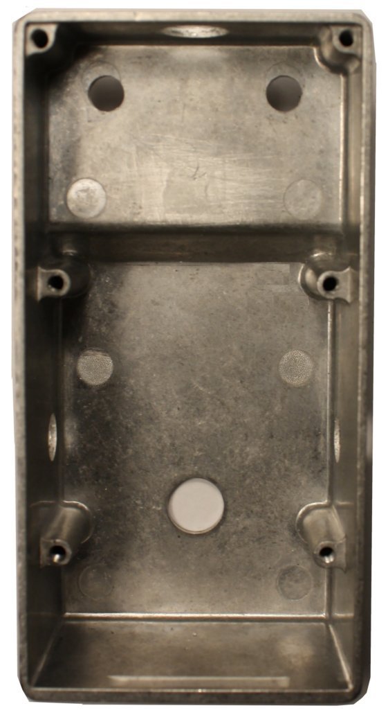
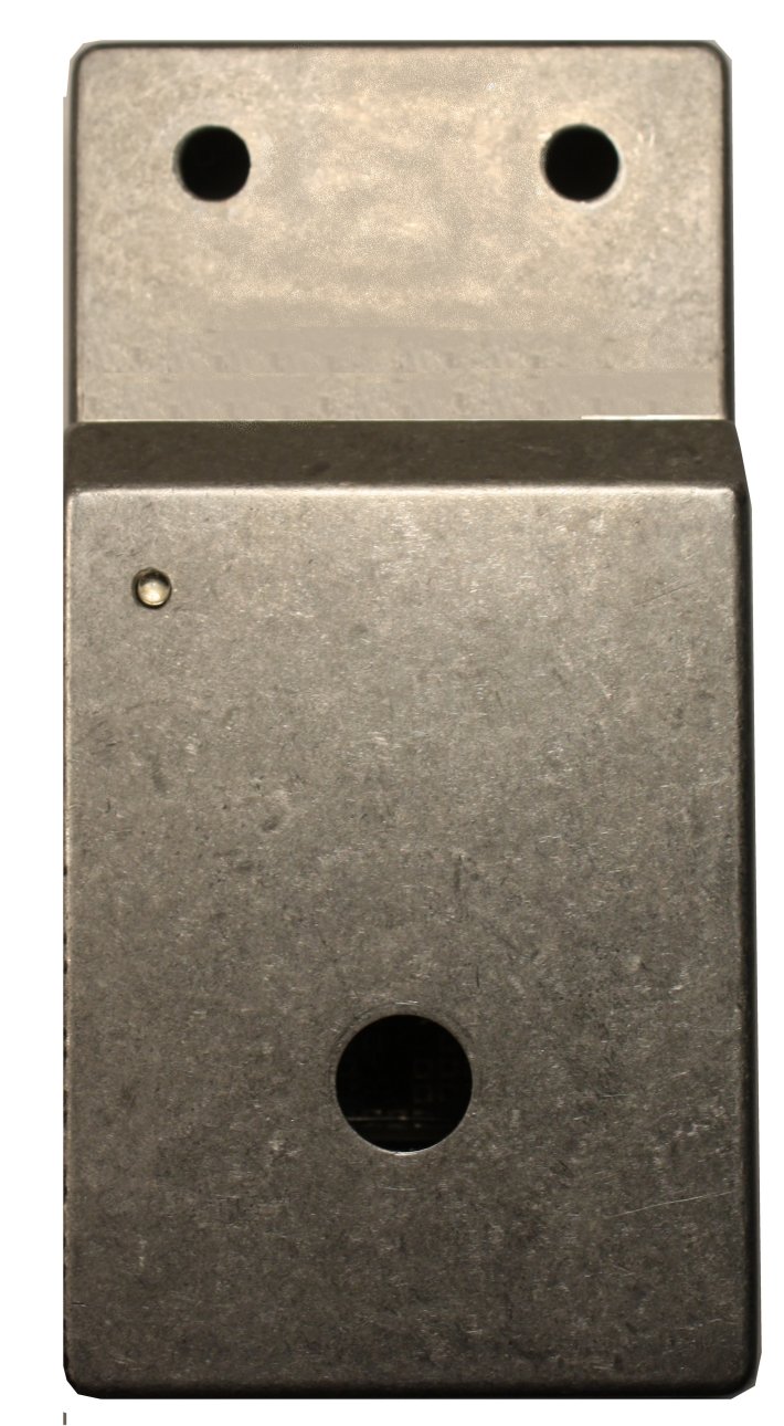
Since I'm starting with the pre-drilled Bare Box # 1, let's take a look at
that and get it prepared for the build by adding holes for the two
potentiometers. I am basing this description on using Alpha's RD901-40 9mm
pots with right-angle PCB pins. You don't have to use those for a two- or
three-knob build, but they are very convenient to work with. Similarly, you
can locate the hole centers by creating a paper template, but it is very easy
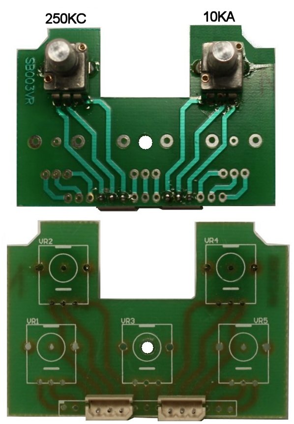
to get exact registration by using the 5-Pot board that I had made for this
enclosure.
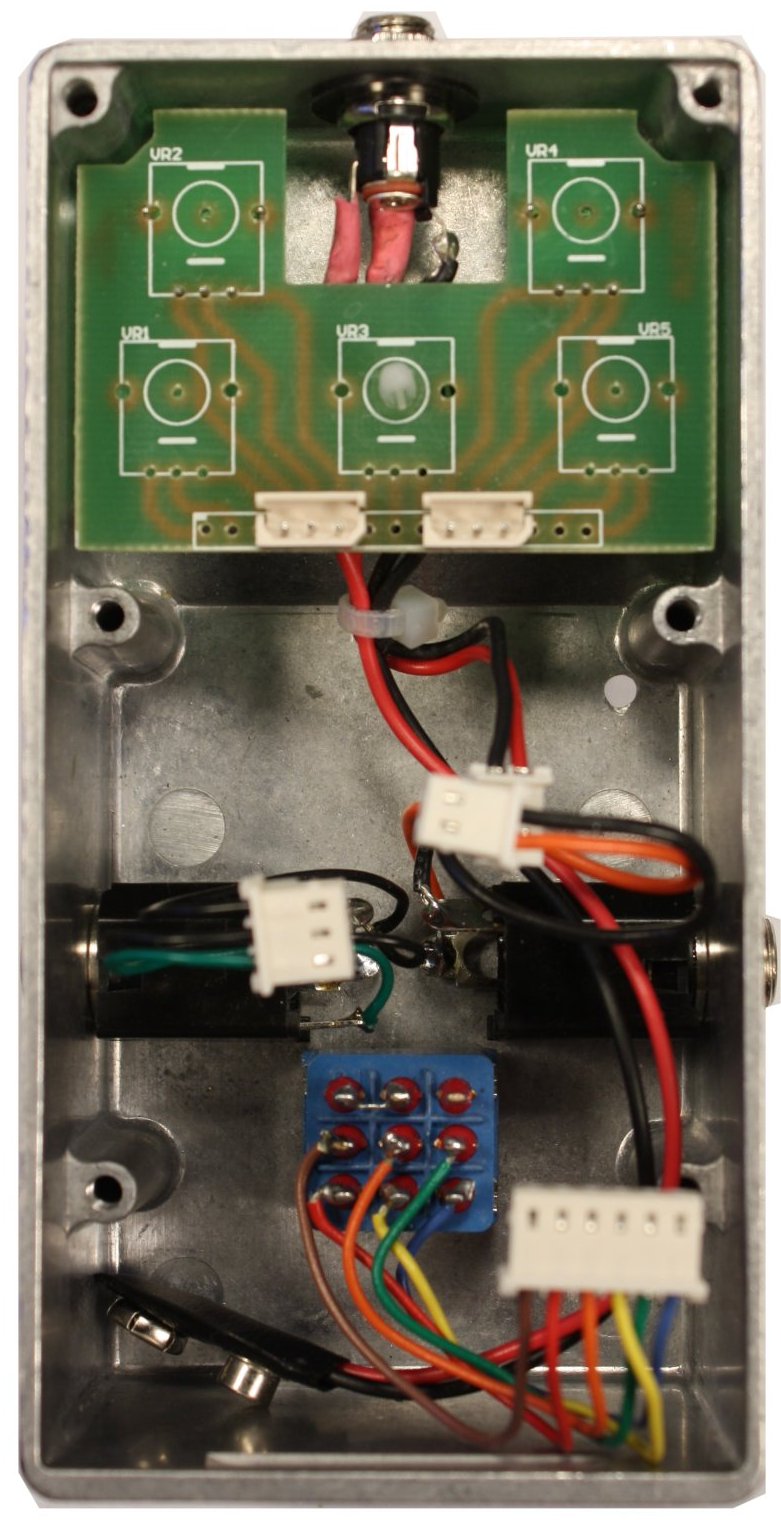
The second pic from left shows the 5-Pot board lying in place in the
"well." Each pot outline has a drilled hole marking the center of the control,
so I used a straight pick to mark the points where I wanted to drill. That was
pretty easy, right?
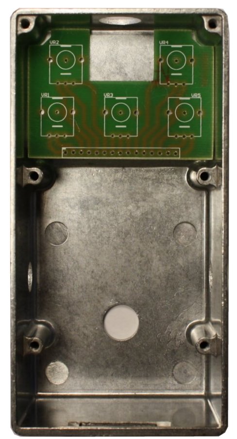
Because the LED is installed on the circuit board, I left drilling the hole
for it till the board is done.
Choices For Building The Board
Here is a complete layout drawing and parts list:
The above layout presumes that you want to build the full "protoboard"
arrangement that allows re-configuring the transistors, so it includes all of
the connection points needed to do that. I will show the jumpering
arrangements later. If you only want to build a single configuration, you can
reduce the wiring and the number of socket pins accordingly:

The perfboard shown in the following pics is my SKU 0355. It's 60 x 60mm
pad-per-hole, sized exactly for the Bare Box # 1. You can, of course, cut to
size a larger piece of stock and drill mounting holes. The layout presumes the
use of Molex headers to terminate input, output, power and stomp switch.
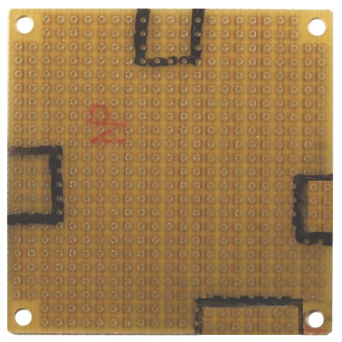
Again, you don't have to go this route. If you do, the first step is to tool
the cutouts in the board for the headers. The layout drawing and the pics
below show the areas that need to be cut away. Mark these carefully with a
Sharpie or similar marker.
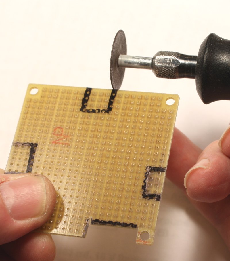
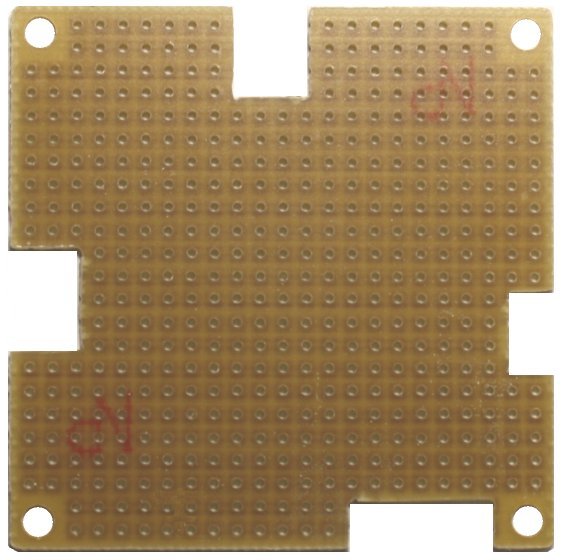
Use any combination you want of cutting, scoring or grinding to create the
cutouts. (IMORTANT
NOTE: Machining epoxy-glass circuit board creates fiberglass dust, which is
noxious stuff! When doing any tooling of the board, wear disposable gloves and
a face mask! If you use a cutoff wheel, eye protection is an absolute must!
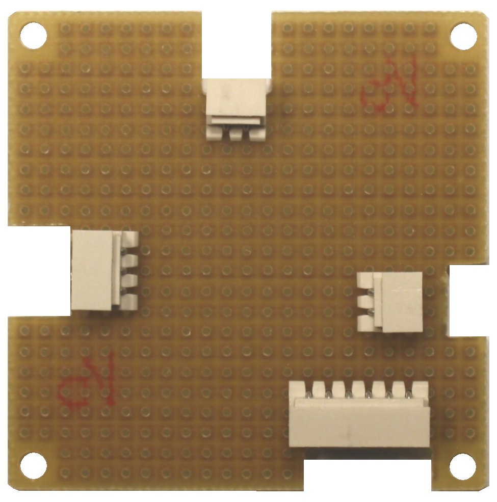
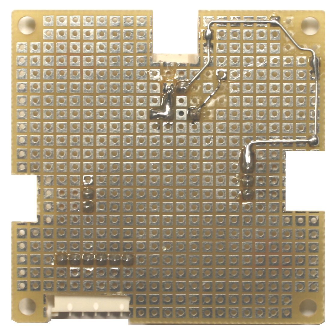
I found that soldering the headers in place first gave me good reference
points for doing the wiring. They are positioned identically in all of the
layouts. Follow the left-hand pic and the layout drawing for the build you
choose, and pay
rigorous attention to where the header pins go.
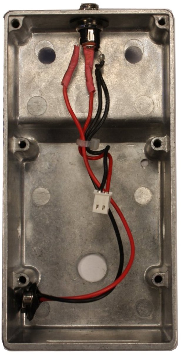
I began wiring with the connection from the negative power input to the
Ring contact of the input jack. Notice that I used the soldering iron to heat
and remove a few pads around the mounting hole? This is important for reducing
the potential for accidental shorts.
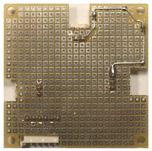
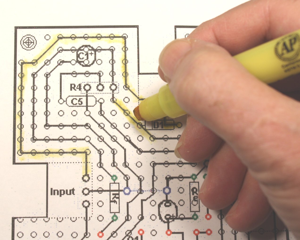
I continued by installing power-protection diode D1. Its anode goes to the
positive power input pin. Then I laid the path
from its cathode (bar side) to one side of where the connection to R4 will be
made. I have colored in the drawing the pads I removed that might short to adjacent
locations. Continue to do this as you wire. As always, I
mark off what I have done with a highlighter.
If you have had some experience working with perfboard, you should be able
to finish the wiring with these few suggestions:
- Dotted lines that connect two pads are bare-wire jumpers on the top
side.
- This being a DIY build, I know that many builders will want to be able to tweak the bias resistors and maybe swap
transistors as well. To make this easier, I used individual pins taken from Mill-Max
single-in-line socket material to create component "sockets." I like the result, and I can stock the unmounted pins if other people want them. The pics following show the idea.
Using a #55 drill, bore out the hole where the pin is to go. That size is just
right to leave part of the copper pad on the board for solder to bond to. Insert the pin and solder it in
place. The resulting construction is almost like a rivet.
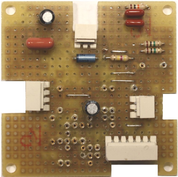
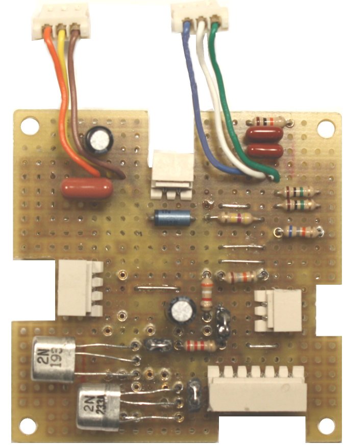
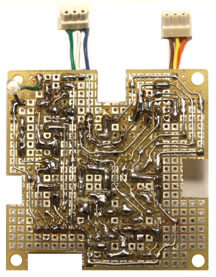
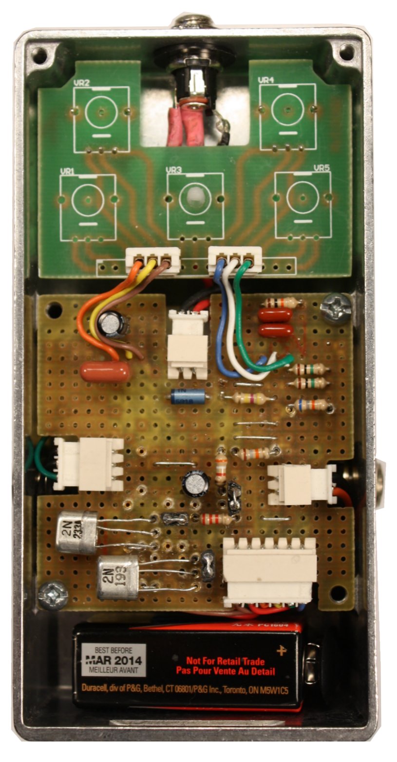
The pic below left is the completed board prior to soldering in place the
connections to the pots and the LED.
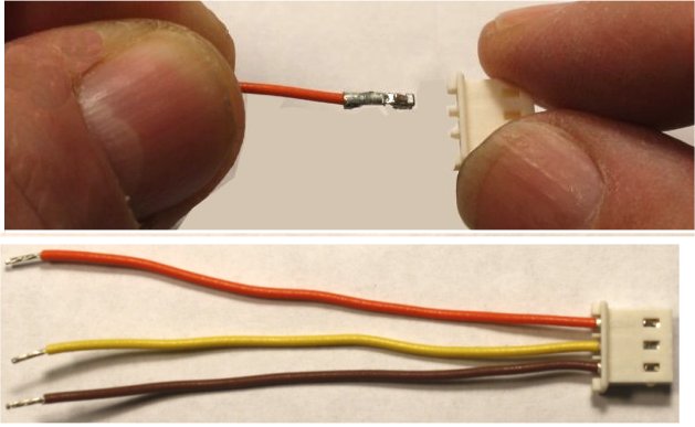
I love these Molex "SPOX" plugs and headers that I have used to make the
off-board connections. I am sure the reason more people don't use them
is that crimping the terminals manually is hard without a very expensive tool.
Pre-assembled connectors for power, input and output, and pre-terminated wires in a variety of colors
are posted in my Stock List, so you can pick colors and create your own
plugs for the pots and stomp switch.
The resistors that are plugged in for Rb, Rc, Rd and Re are the nominal
values that I worked out when I came up with the idea for the Oh My Darling.
This article describes how I got to
them and gives some ideas for selecting the transistors. Raw stock is available on the Stock List
and audited pairs will follow soon. The right-hand pic shows the board
with connectors installed for the pots, transistors installed for the Oh My
Darling and jumpering done for that version. The layout drawings that follow
show the jumpering possibilities that I worked out. When setting up the
Sziklai, note that the transistor orientations are reversed from the Oh My
Darling.
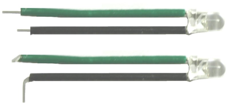
I chose a 3mm LED for this build. To install it, I first covered its leads
with spaghetti. A couple of scraps of installation fit fine. I left about 1/8"
bare on the negative lead, a little more on the positive. Then I bent the
leads at right angles to each other before soldering to the pads on the bottom
of the board. I eyeballed the location for the LED hole by holding the board
in place in the enclosure. With that hole drilled, the LED and the board fell right into
place.
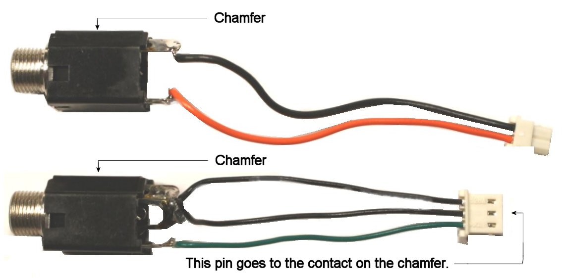
I chose shrouded jacks for this build, as used in most "name" pedals. These
have a chamfer on the sleeve pin edge, which is helpful for identifying the contacts. Pay
close attention to which contact of each jack is soldered to which contact of
its associated plug.
The pot board is prepared by soldering the pots and headers in place and
boring out the center hole of location VR3. This will pass a standoff for
stability when the pot board is installed. You may substitute 250K audio for
R2, though I found that the "spread" of control is better with reverse audio.
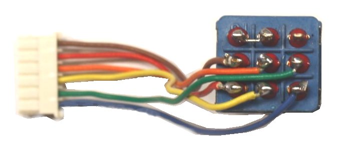
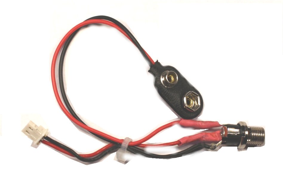
The stomp switch and DC power connector are prepped in the same way as the
input and output jacks by wiring connectors to them. Any panel-mount DC power
jack is OK, but the pre-drilled hole has to be enlarged for the all-plastic
types. If you use my SKU 0612D as shown here, the shoulders of the washers
need to be filed down slightly because the panel in front is a little thinner
than on some other enclosures. The notes in the layout
drawing should help with getting the connections right.
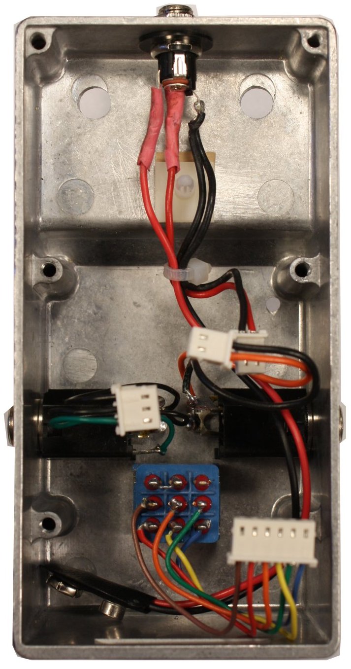
Put It Together To Test
I worked from front-to-back and bottom-to-top as shown in the following pics.
Before inserting the pot board, set a standoff in place without exposing its
adhesive as shown in the second pic. Plug in the off-board parts, install the board
with minimum screws for now and screw nuts on
the pots finger-tight.
At this point, I connected my gear at got...nothing. So I did what I tell
everyone else to do: lifted the works out, started testing continuity
point-to-point and marked off connections with a highlighter. I found a
connection that I had forgotten to solder and a couple of shaky joints on the
pot board. Fixed those, set up again and got action. The drawings above are
exactly what I built, so you should be good if you follow precisely. If you
have built a Rangemaster, the transistor voltages at Collector, Base and
Emitter are the same.
Finishing
The pluggable construction makes the Oh My Darling very easy to strip down. I prepped the enclosure in the usual way: Sand to
600 grit, acetone wash, spray paint, add decals and clear coat with Krylon
lacquer. Incidentally,
if you are not comfortable with drilling and coloring, pedalpartsplus.com will
do these steps for you. Their prices are reasonable and the quality is quite
good.
I rested the case on a soft cloth so that I wouldn't scratch the finish
while poking around with a meter. I hope you enjoy being able to build in this
modular fashion. Comments and suggestions are welcome at smallbearelec@ix.netcom.com.
Parts List/Bill Of Materials For The Oh My
Darling
|
Reference or Quantity |
Description |
Small Bear SKU |
|
|
Fixed resistors are ¼ watt, 5% tolerance, carbon film or 1% metal film. |
|
|
R1, R5 |
1 meg |
|
|
R2 |
250K Reverse Audio Taper Potentiometer |
1012A |
|
R3 |
470K |
|
|
R4 |
10K
Audio Taper Potentiometer |
1012A |
|
R6 |
10K (for a 3mm high-brightness clear LED) |
2304 |
|
Rb,Rc,Rd,Re,Rf |
Selected bias resistors (see text) |
|
|
C1 |
100 mf. 16 volt radial
electrolytic |
1404 |
|
C2 |
.0022 mf. poly-film or mylar |
1150 |
|
C3 |
.015 mfd. poly-film or mylar |
1101B |
|
C4 |
47 mf. 16 volt radial electrolytic |
1404 |
|
C2 |
.22 mf. poly-film or mylar |
1103B |
|
D1 |
1N5818 Schottky diode |
2215A |
|
Q1,Q2 |
Selected Germanium or Silicon (see text) |
|
|
|
|
|
|
|
Pot Board and Connectors |
|
|
1 |
"5-Pots" Board |
0353 |
|
1 |
3/8" Mini-PCB standoff |
0415N |
|
2 |
Molex 3-pin vertical headers |
0614S |
|
2 |
Molex 3-pin plugs |
0614U-2 |
|
6 |
Terminated leads |
0614O |
|
|
Main PCB and Connectors |
|
|
1 |
Pad-per-hole perfboard or PCB |
0355 |
|
2 |
Molex 2-pin horizontal headers |
0614R-1 |
|
1 |
Molex 3-pin horizontal header |
0614S-1 |
|
1 |
DC power connector |
0614M |
|
1 |
Input connector |
0614N |
|
1 |
Output connector |
0614N1 |
|
1 |
Molex 6-pin horizontal header |
0614T-1 |
|
1 |
Molex 6-pin plug |
0614U-3 |
|
1 |
Strip of single-in-line socket pins |
0706 |
|
6 |
Terminated leads (for the stomp switch) |
0614O |
|
|
Bare tinned wire |
0509 |
|
|
Parts For The "Shell" |
|
|
1 |
Bare Box #1 Enclosure |
0350 |
|
J1 |
1/4" Shrouded Stereo Jack, Switchcraft #112B or similar |
0604 |
|
J2 |
1/4" Shrouded Mono Jack, Switchcraft #111 or similar |
0603 |
|
J3 |
DC Power Jack |
0612D |
|
S1 |
3PDT stomp switch |
0200 |
|
2 |
Knobs for ¼" shaft |
|