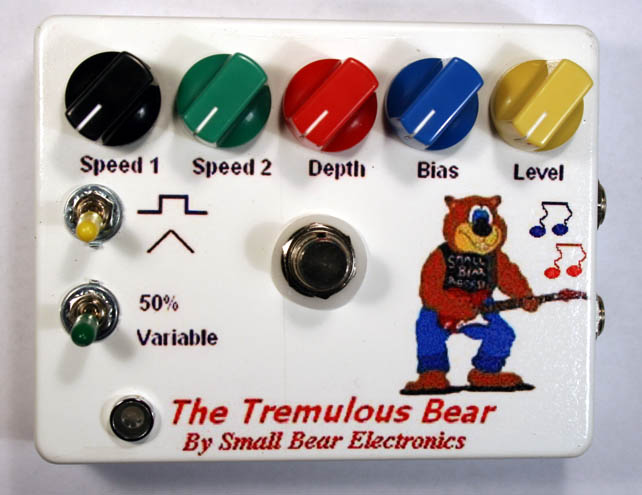
 The Tremulous Bear is a boutique-quality tremolo that can be constructed from
readily-available components. It does all of the good things you would expect of a modern, flexible trem: traditional Fender-style chop, subtle background quavering and weird modulations. The LFO is an interesting design; you get choice of triangle or square wave and lots of room for hacking and mods.
Small Bear offers a complete
kit that includes a
ready-to-solder PC board. This article describes a perfboard version for
advanced builders and includes technical details on how the pedal works. If you
bought the kit, here's a link to the instruction
manual.
The Tremulous Bear is a boutique-quality tremolo that can be constructed from
readily-available components. It does all of the good things you would expect of a modern, flexible trem: traditional Fender-style chop, subtle background quavering and weird modulations. The LFO is an interesting design; you get choice of triangle or square wave and lots of room for hacking and mods.
Small Bear offers a complete
kit that includes a
ready-to-solder PC board. This article describes a perfboard version for
advanced builders and includes technical details on how the pedal works. If you
bought the kit, here's a link to the instruction
manual.An early version of the Tremulous Bear originally appeared in the August, 2001, issue of Gernsback's Poptronics magazine. This redesign is similar in concept but much easier to build. Here are a few sound clips:
How It Works
The Tremulous Bear gets its time-tick from a somewhat unusual setup of the popular 555 timer. The CMOS version is used here for its low current drain. For those who have never poked inside this chip, here's a look and an explanation of what goes on:
IC2 is wired as the LFO. The square wave output at pin 3 feeds voltage divider R5-R6, which sets a suitable level to feed the modulator. Capacitor C9 softens the edges of the waveform, which helps suppress audio ticks. The triangle wave at pin 2 controls the gate of Q1, a MOSFET connected as a source follower. The high input resistance of the MOSFET isolates the timing capacitor from the modulator, and it outputs an exact replica of the charging voltage across R7. Toggle switch S2 feeds the selected control signal to modulator transistor Q2, through potentiometer R8 and blocking diode D2. D2 keeps voltage divider R9-R10-R11 from loading either control signal. Potentiometer R11 sets the quiescent bias of Q2. As the voltage of the control signal rises and falls, so does the bias on the base of Q2 and therefore the brightness of the LEDs. LED1 gives a visual indication that the effect is operating, while LED2 excites photocell LDR1. The LDR may be a separate component or part of a photocoupler assembly.
The "Var" Switch
For greatest flexibility, it's desireable for a tremolo to offer control of the duty cycle of the controlling signal, i. e., what percent of the time is it "on" and what percent "off"? Getting an uneven duty cycle from a 555 oscillator is easy; it's getting equal on and off times that takes a little doing.
Looking back to Fig. 1, the timing capacitor charges through two resistances, RA + RB, but only discharges through RB. Because of this, we can't get equal charge and discharge times. This is OK if we want an odd effect, but we also need a way to get a "normal" 50% duty cycle. Diode D1 is switched in or out to take care of this problem. With S1 open (the "Variable" position), C7 charges and discharges through two resistances. With S1 closed (the "50%" position), C7 charges mostly through R1 + R2 because the forward resistance of the diode is much lower than the combination of R3 and R4. C7 then discharges entirely through R3 and R4, because the diode blocks in its reverse direction. Since D1 creates separate charge and discharge paths for C7, it is easy to set R1 and R3 for equal on and off times.
The Modulator
The design of this stage is based on the Commonsound Tremulus Lune. IC1a is a simple amplifier that provides a constant input impedance for a guitar. The resistance of LDRl determines the input level to IC1b. IC1b provides a convenient way to match the output level of the circuit to your taste, and a low output impedance for easily driving effects loops.
Bypass and Control
Switch S3 is a DPDT alternate-action type. It provides true bypass with control of the in-use/modulation indicator LED using what is commonly called the "RAT bypass" circuit. When S3 is in bypass mode, level control R25 grounds the base of Q3, a darlington transistor, and so cuts it off. This floats the emitter of Q2 and prevents illumination of the LEDs. I have done extensive testing of this part of the circuit, and I have found the switching both positive and completely silent.
How To Build It
The number of components and the tooling requirements make the Tremulous Bear an intermediate-level project. Before trying this one, you should have built at least one pedal that required tooling of a metal case and working with perfboard or Veroboard.
One caution to hobbyists who have never built a tremolo: the hardest part of making a good trem is keeping the LFO from introducing thumps or ticks into the audio output. It is doubly difficult when using the 555, because the switching action of the comparators puts noise on the power supply rails and produces harmonics that go into the RF region. Notice that the board layout clearly separates the LFO from the modulator. This also makes it easy to physically separate the leads that go off-board from the modulator from those for the LFO. If you hand-wire or create a different board layout, I strongly suggest that you follow these guidelines. If you build the Tremulous Bear as shown here, youll find that it is tick-free.
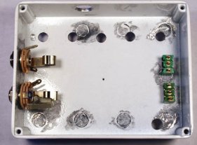
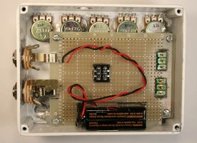
Here is a look inside the case:
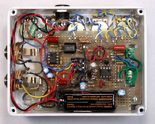
I managed to scrunch my first prototype onto a medium pad-per-hole board, but I chose to spread this one out to a large-size for ease of construction.
Begin by following my instructions for building a 5-knob Shell, but use this drilling template. You want to create the tiny pilot hole for the stomp switch, then holes for the pots, toggle switches, LED bezel, input and output jacks and power jack.
Note: The enclosure shown here is a pre-powder-coated white. If you start with an unpainted box, don't do any painting or decorating yet. If you are working with a pre-coated box, make sure that you grind or sand away the color around the holes for the input and output jacks. When you have finished drilling the holes and grinding out any molding artifacts (step 7 in building the shell), temporarily mount the jacks and the toggle switches. The result should look like this:
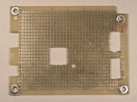
The next step is to tool the blank perfboard, create cutouts for the jacks and switches, and establish the locations for the mounting studs. The layout drawing and the detail photos show the areas that need to be cut away. Mark these carefully with a Sharpie or similar marker. I left the cutout for the battery for later when doing this proto.
Use any combination you want of cutting, scoring or grinding to create the cutouts. (IMORTANT NOTE: Machining epoxy-glass circuit board creates fiberglass dust, which is noxious stuff! When doing any tooling of the board, wear disposable gloves and a face mask!)
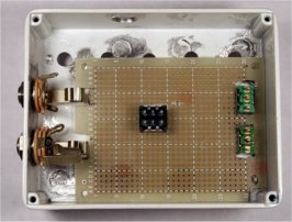
After you have done the cuts, drill a 1/8" hole at index R17 for the LED indicator wires. Then bore another 1/8" hole at the lower right corner for a mounting stud. If you have made the cuts correctly, the board should slip right over the switches and down to the floor of the case, like this:

While holding the perfboard in place, bore through the pilot hole that you created earlier on the top of the case. This may create a new hole in the board, or the drill may go through an existing hole. Either way, you now know the starting point for creating the cutout for the stomp switch. Mark this point with a Sharpie.
Now mark the center of each of the corner mounting holes for the board. Using carborundum paper (or a Dremel tool if you have one), sand thoroughly over and around the mark for each mounting hole to create a cleaned location for a mounting stud.
Using a Unibit, or twist drills and reamer, bore the hole in the case for the stomp switch. Drill a small pilot hole in the board at the point you marked for the switch cutout, and slowly enlarge it and square it off. Mount the switch temporarily. If your cutout is just right, the board will once again slip into place over the switches:
You are ready to install the mounting studs. With 3/8" studs, I found that board just barely cleared the cans of the pots. To provide a little more room between them, use quick-setting epoxy cement to attach two flat washers under each mounting hole as shims:
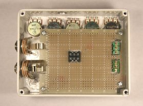
Temporarily install screws and studs in the mounting holes. Re-position the board, and make sure that the flanges of the jacks have room to move freely when you insert a plug. The result should look like this:
Glue the studs in place and reinforce with more epoxy in the usual way.
Remove the board, tool the cutout for the battery, and install either a battery clip or a bump-on attached to the cover to keep the battery from shaking:
Now disassemble, and paint if you need to or just do your decals. The shell is finished, and you are ready to stuff the board. Here's the layout, and a parts list: