This article describes the construction of a "shell," or housing for a stompbox, based on a "BB-size" case oriented horizontally in the "BOSS" style; input is on the right, output on the left. The layout provides for open-frame metal input and output jacks, up to five 16mm controls with #1510 or similar knobs, an in-use LED and a DC power jack. It accommodates a "medium" pad-per-hole perfboard (371 holes/1.85" x 2.83"), and presumes that the bypass switch will either fit through a cutout in the center of the board or be on-board in the form of a tactile switch driven by an actuator. I have included a procedure for getting correct registration repeatably when doing bypass-on-board. While I developed this shell in redesigning my Bear Face pedal, I believe it will be useful to others as a platform for other relatively simple effects. Here is the procedure:
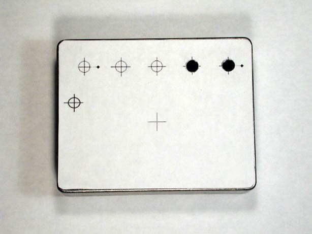
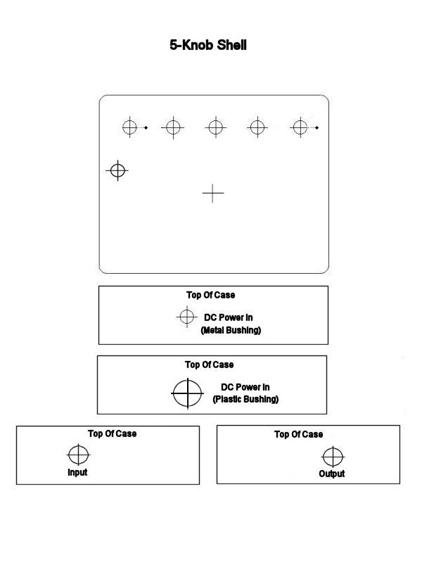
- Download and print the drilling template. With a sharp scissor, cut out the piece for the top of the case.
- Using double-sided transparent or masking tape, attach the template to the case.
- Using a scribe or center-punch, mark the centers of the holes for the pots and the LED Bezel and drill them. I used a Unibit for this, but regular twist drills are also fine. The hole sizes are 9/32" for the pots and 5/16" for the LED Bezel. Don't drill the center hole for the stomp switch fully yet. Mark the exact center and drill with a #59 or #60 drill.
-
If you do a five-pot pedal, you may want to make use of the anti-rotation
tabs of the pots. By drilling these holes, you avoid possible problems
later with shorting of a lug to the chassis, but you'll have to fill in the
holes later with Bondo. I found a better way to deal with this issue, but
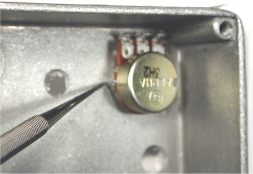
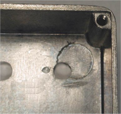
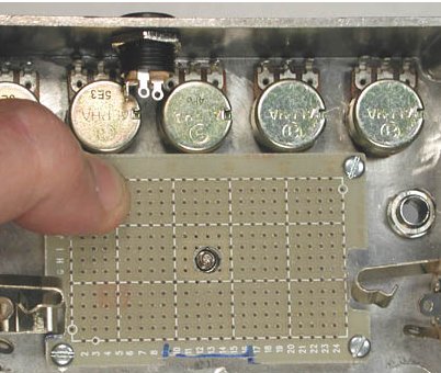
you need a Dremel tool to make use of it: As shown in these pics, slip a pot
into the rightmost position temporarily, eyeball the point where the tab
will contact the case and mark or scribe the location. With a 3/32" drill,
start boring a hole, but don't go in more than about a third of the way. Now
make like a dentist: use a ball-type Dremel cutter to widen the cavity so
that the tab fits right in. It is OK to file the tab down a little to make
it fit. Be sure that the control mounts flush to the surface of the box.
-
Decide whether you want to use a metal or plastic power jack, cut out and
attach the appropriate template and drill this hole. If you use a metal DC
power jack, the hole is 5/16". However, you may want to provide for
insulating the metal bushing from the chassis. In that case, you either have
to enlarge the hole slightly to fit shoulder washers (I am still evaluating
these) or create a "platform" using Bondo (see the techniques in the article
on the Small Wart). The template gives a center position for the hole that
will allow either. If you use the standard plastic "BOSS-style" power jack,
the hole is 1/2" in diameter.
- Create the 3/8" diameter holes for the input and output jacks.
- On the inside, grind down any lettering or molding artifacts that would prevent a part from having a flat purchase.
-
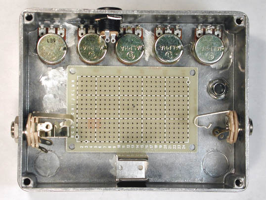
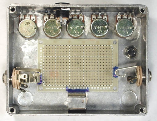
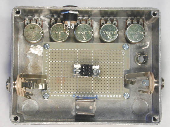
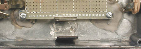
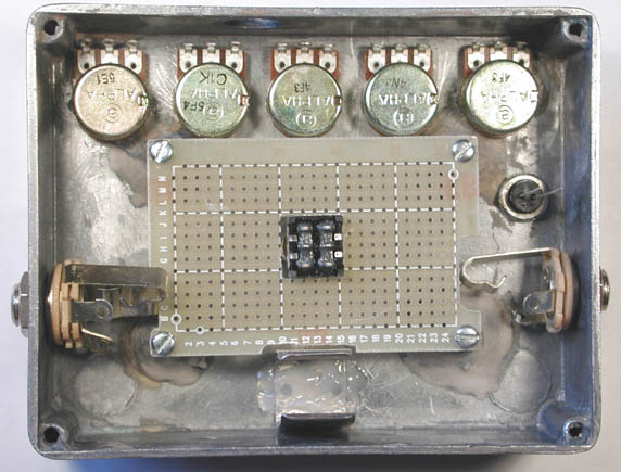
Mock-up the case with the parts you have tooled for so far, and add the
battery holder. Position the perfboard by sticking a drill bit through index
H13 and through the hole in the top of the case. The result should look like
this:
-
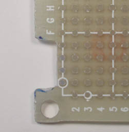
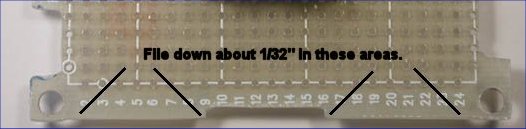
You will need to file or grind cutouts in the edges of the board to fit the
flanges of the jacks and the battery clip. Carefully mark these now with a
felt-tip pen:
-
Use any combination you want of cutting, scoring or grinding to create the
cutouts for the jacks.
(IMORTANT NOTE: Machining epoxy-glass
circuit board creates fiberglass dust, which is noxious stuff! When doing any
tooling of the board, wear disposable gloves and a face mask!) The detail photos indicate how much material to remove. Temporarily install screws and studs in the mounting holes of the
board. Note:
1/4" studs are fine if you will be using a standard stomp switch; 3/8" are
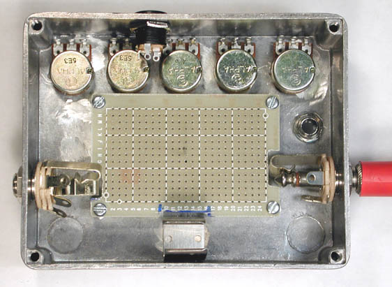
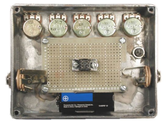
required for bypass-on-board. Re-position the board, and make sure that the flanges of
the jacks have room to move freely when you insert a plug. The result
should look like this:
- Now you can drill the hole for the stomp switch, centering on the tiny starter hole that you drilled in the beginning. Any switch you are likely to use (Carling, Alpha DPDT, 3PDT, will require the same 15/32" hole.
-
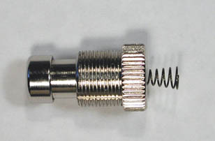
How you proceed from here depends on the kind of stomp switch you want to use.
I'll show you how to set up Bypass-On-Board first and then offer suggestions
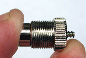
for installing regular switches. To start, remove the hardware from the switch
actuator and be sure that the knurled bottom cap is screwed as far as possible
onto the threaded bushing. Push the plunger all the way in, and use a diagonal
cutter to cut off the spring right at the end of the push-rod around which it
is wrapped:
-
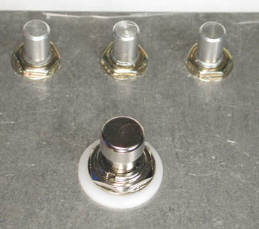
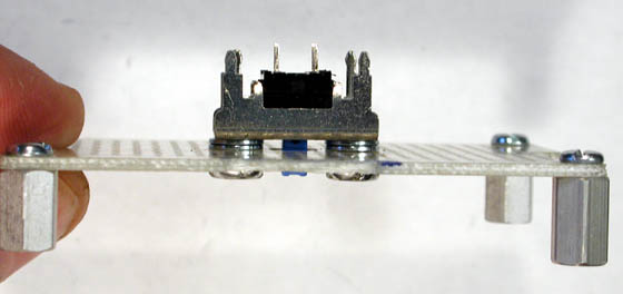
Install the actuator in the case with no washer or nut on the inside. On the
top, follow with a nylon washer, lockwasher and nut:
-
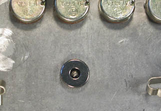
Drill the hole at index H13 on the perfboard out to 7/32". Set the perfboard
in position. Press the actuator from the top, and the push-rod should poke
cleanly through this enlarged hole:
-
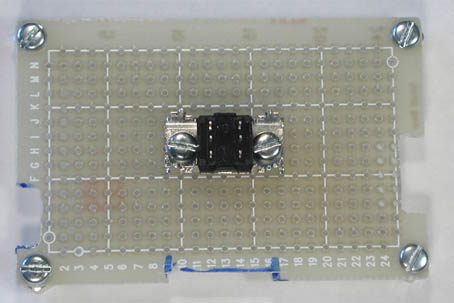
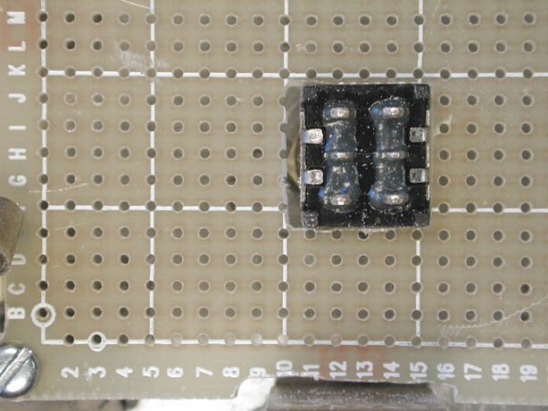
The following directions apply for the E-Switch DPDT tactile switch p/n
1XJN002UEE on my
stock list. If you use something different, you may have to make other
arrangements. On the board, bore indexes H10 and H16 out to 1/8". Screw a 4-40 x
1/4" screw fully into each threaded flange of the mounting bracket of the
switch. Lay the switch down in the new holes on the board and secure each screw
with a 4-40 nut finger-tight:
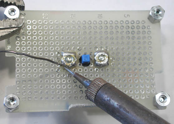
- Soak a Q-tip in acetone and thoroughly clean the surface of each nut and the area around it. Carefully close the container of solvent, and then heat up your soldering iron.
-
Using as little solder as possible, bond the nuts to the pads of the board.
Don't let the solder get into the threads:
-
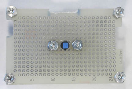
The switch has to be shimmed to its proper height. Remove the screws, and
reassemble with two #4-40 washers between each flange of the switch and the top
of the board:
- The next step is to attach the board assembly and studs to the case. Remove the switch, and thoroughly clean the areas where the studs will rest. I do this by sanding with 220 grit carborundum paper and cleaning up with acetone.
- Bearing in mind that you will be baking the case at 150 degrees F after you paint it, check the temperature spec of the adhesive you use before proceeding. I used Bondo auto-body filler, which is specified as being able to tolerate up to 180 degrees continuous. Mix a small amount of adhesive, and apply to the bottoms and sides of the studs. Gently set the board down and orient it so that the center hole in the board is centered on the opening of the actuator. Give the adhesive a couple of hours to set.
-
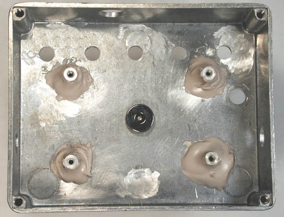
Remove the board and all of the hardware, and reinforce the studs with more
adhesive. The result should look like this:
- When the adhesive has fully cured, reassemble the switch to the board, screw the board in place and test the operation of the actuator. If the switch doesn't activate because two shims on each side position it too high, you may have to remove shims.
-
Remove the board again and reduce its width slightly where the battery clip will
fit by filing as shown here:
-
Mount the board again, and prepare the battery clip for mounting by cleaning its
bottom surface thoroughly with acetone. Do the same to the area where it will be
bonded. Attach the battery clip initially with small amount of quick-setting
epoxy cement. Position the clip as in this pic so that the upper edge is just a
hair inside the cutout:
- When the epoxy has cured, insert a battery put the cover of the case on and make sure that the "lip" of the cover seats properly between the flange of the battery clip and the wall of the case. Remove and re-position the battery clip if necessary, and reinforce it with more epoxy.
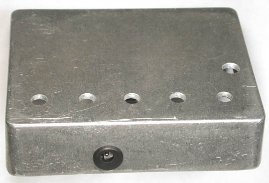
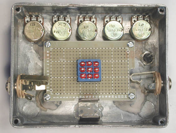
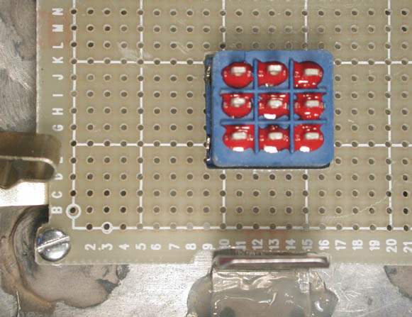
- Disassemble, paint and decorate! When you have satisfied all of your artistic desires, assemble the shell with all of the controls. Here's a last pic of one of my prototypes, ready for the board to be stuffed:
Building With A Regular Stomp Switch
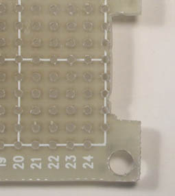
...is much easier than doing the Bypass-On-Board thing. Once you have drilled the 15/32" hole in the case, mount the stomp switch temporarily. Bore out the hole in the board at H13 to 1/4", and grind/file it to a cutout that lets the switch pass through. Here is an overall pic showing the Alpha switch, and a detail pic showing where to cut:
You can also use a 3PDT:
When you have the cutout done, you can continue with step 19, attaching the mounting studs for the board.
I hope you find this a useful and flexible platform for many effects, and I welcome comments and questions at smallbearelec@ix.netcom.com.