A few notes to builders who are "rolling-their-own" for technical or economic reasons:
I specify a number of made-to-order parts and specific modular connectors, because part of my purpose was to allow a novice builder to produce a result that is comparable to a manufactured product. If you have some experience, or some help, you can adapt the ideas shown here to accommodate locally-available parts and materials.
JFETs, are notoriously variable in their essential parameters. But the good news is that you have choices about what devices you use and where to get them:
- If you bought the breaboarding kit, we included a pair that are guaranteed to fall within specified limits.
- We have lots of unsorted stock that you can buy from and sort your own.
- We offer some sorted devices.
- You can buy elsewhere and sort your own.
Like many of my designs, this one can be built more "from scratch" or more "paint-by-number" depending on how down-and-dirty you want to get. These instructions are centered on the perfboard build, so click here if you bought the PCB or the full kit.
The full pedal is a fairly complex build, but it is also entirely possible to build a more limited one-stage "Junior Bare-Ass" (?) using these ideas and on the same platform. I'll discuss this in detail later.
Breadboard To Box - What Is Involved?
If you followed the breadboard build to its end, you have a working circuit, complete from input to output something like Figure 1.
Just as for the Ursa Minor, bypass, power switching and in-use LED need to be added to make this into a buildable design for a finished pedal. If you are not familiar with true-bypass/in-use LED and battery/external power switching, please read the beginning of the Ursa Minor project article before you go further.
Figure 2 is the entire schematic including power and signal switching and in-use LED.
Schematic To Layout
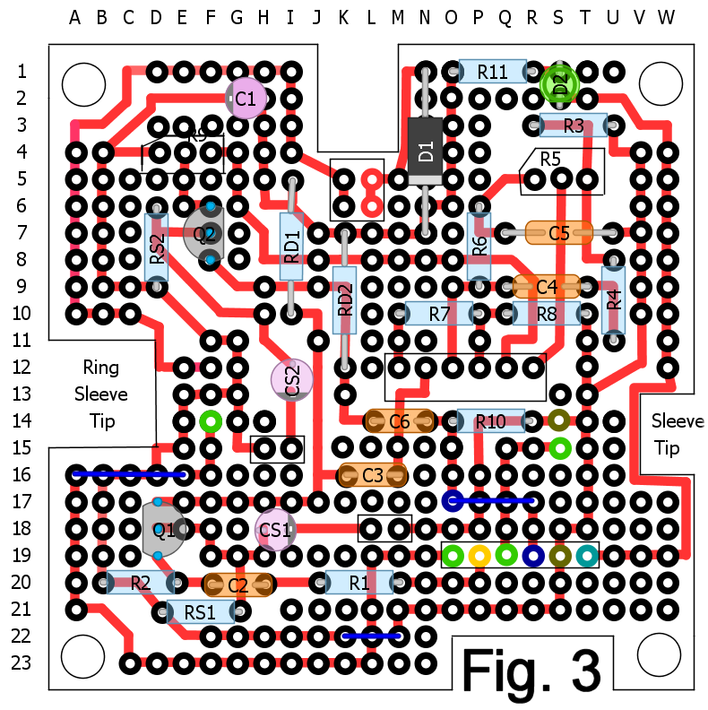
A schematic shows the logical relationships between components, but it doesn't necessarily show physical relationships--where components are mounted in relation to each other. Once a circuit has been proven to work, a designer's first job is to translate the schematic to a suitable layout on a chassis or circuit board. While I have used a variety of graphics packages to do layouts in the past, I did Figure 3 using DIY Layout Creator. It is freeware, and an absolutely fantastic tool--highly recommended. It is optimized for laying out circuit patterns on media typically used for DIY, in this case pad-per-hole perfboard.
Perfboard?
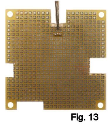
Perforated circuit board, or perfboard as it is commonly called, is a convenient material for building a hand-wired prototype. Each hole on the bottom of the board has a tinned copper pad to which solder can bond. This type of stock is called, appropriately, pad-per-hole perfboard. Component leads are inserted through the holes and soldered in place on the opposite side. Connections are made with short lengths of bare wire. This board (Fig. 4) is 60 mm x 60 mm with a 529 hole (23 x 23) grid.
Understanding The Layout Drawing
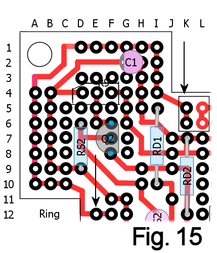
The red lines are point-to-point soldered connections on the underside of the board; you are seeing them in "X-Ray" view as though looking through the top. The thin, blue lines are bare-wire jumpers on the top (component) side of the board. I have added an alphanumeric index so that every one of the holes in the board can be identified by a letter-and-number coordinate. I use the indexing on the board to refer to the position of every joint in the layout drawing. You can locate the components and do the wiring "by the numbers".
The .DIY file can be downloaded from here.
Some DIY builds are entirely
paint-by-number, which I don't like--they don't teach much. This build will
include some hand tooling, the amount depending on whether you house in a
pre-drilled
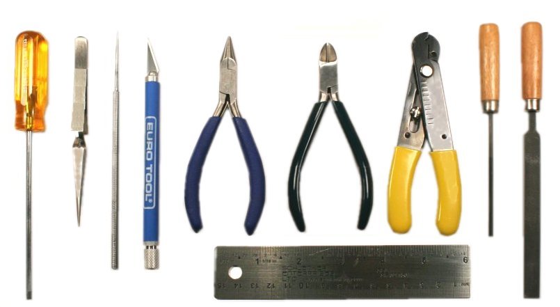
Bare Box #1 or something else. Before you begin, let's make sure that you have all the tools you
need. You'll need a few basics:
For finishing the case you'll need:
- 220-grit and 400- (or finer) grit carborundum paper
- Acetone, denatured alcohol
- Spray primer and enamel
- Decal stock or decals
- Clear lacquer like Krylon
These tools, and many others, are available in my Stock List.
Jn designing the "Breadboard-To-Box" series, I came up with a standard layout for signals, power and in-use LED control for the 60 x 60 pad-per-hole board. It makes the process of designing and building very systematic and so easier and less susceptible to mistakes. I'll begin this build by walking you through tooling the board and laying down those essential connections. For the beginners, I'll show exactly what they correspond to in the schem so that you get a better understanding of how things work.
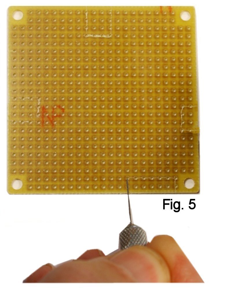
I'm presuming that you'll be building either in a Bare Box #1 or other small enclosure, so it helps for the board to have cutouts to feed leads for signals, power and LED control. Begin by printing a copy of the layout drawing and, referring to the coordinates for the cut-out areas, use an X-acto knife to mark the outlines of the areas that need to be cut away (Fig. 5).
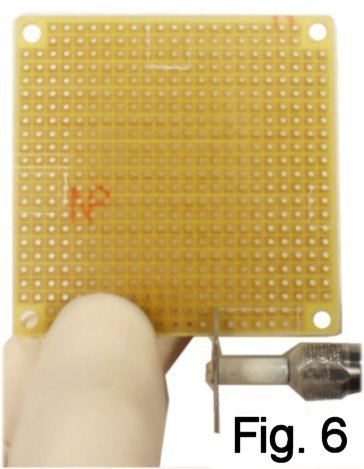
If you have or can borrow a Dremel tool, a cutoff wheel will make the vertical cuts quickly and easily (Fig. 6). However, be aware that the dust that this operation throws off contains fiberglass. If you go this route, WEAR GLOVES, GOGGLES AND A FACE MASK!
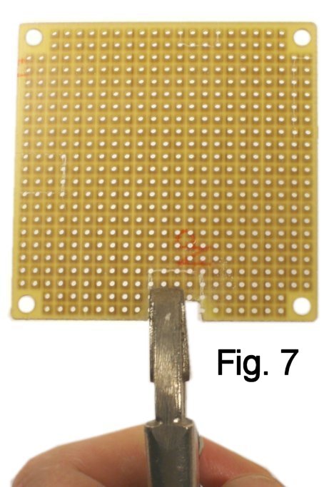
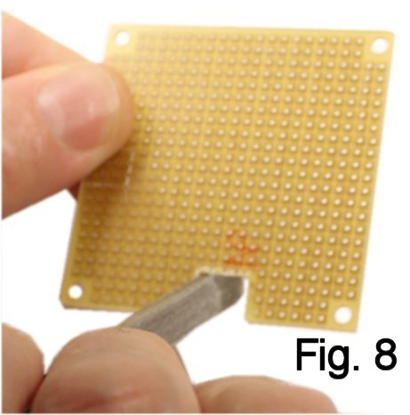
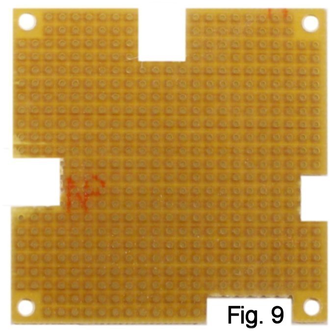
If you are limited to manual tools, continue using the knife and score each line that you have marked a dozen times. Then use pliers to bend and snap on the score lines, "nibbling" a little at a time (Fig. 7). Clean up the edges with a flat file (Fig. 8) and you should wind up with a piece that looks like figure 9.
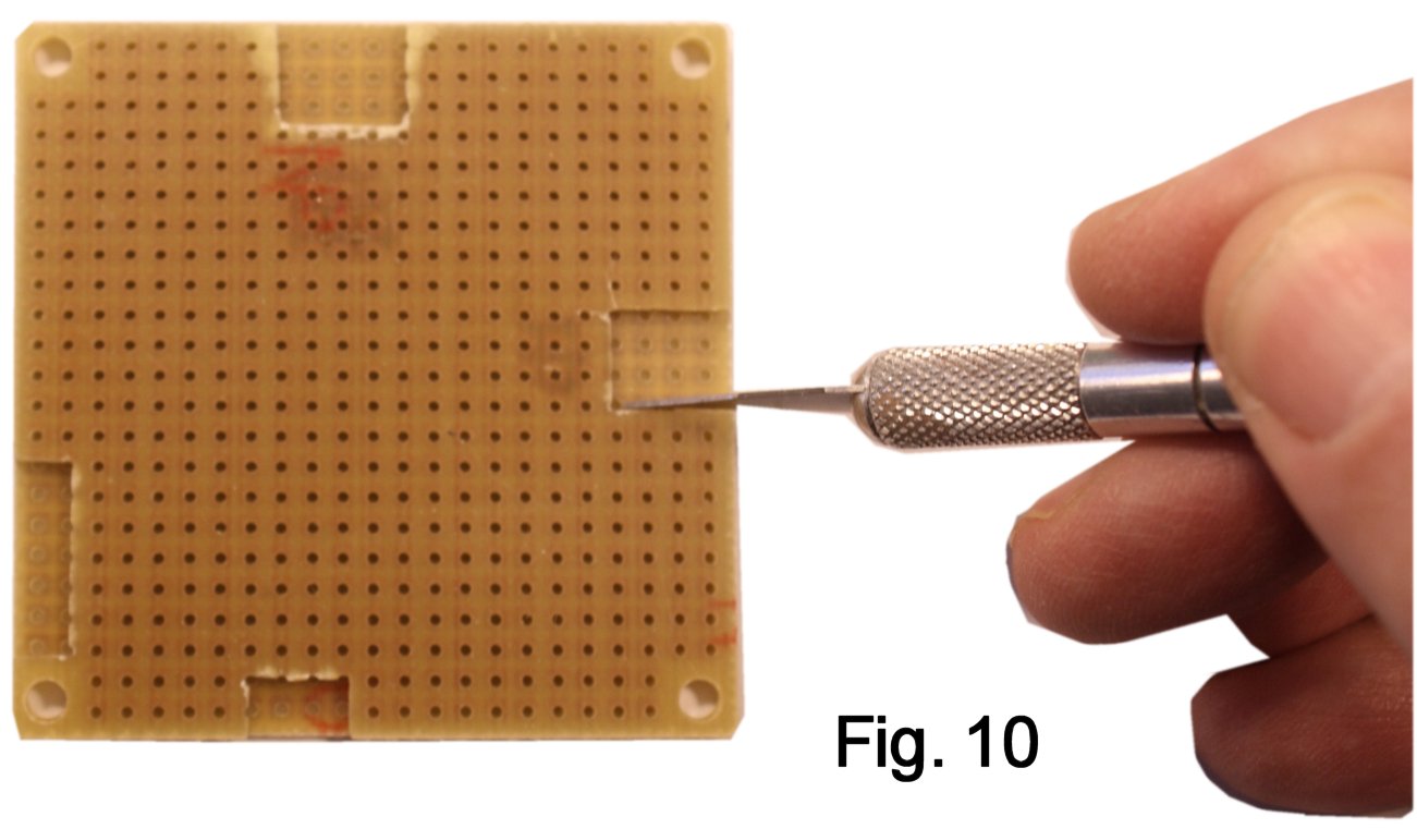
Tip: If you find that you like this method of construction, cut out an extra 60 x 60 board and save it as a template for marking out the cuts on future builds (Fig. 10).
In the directions that follow, I presume that you have learned to solder fairly neatly. If this is your first build and your first time soldering something, please back up and practice making a few joints on something that you can throw away before proceeding.
While you don't have to use them, I have really been pleased with the results I get using Molex SPOX connectors and housings. They make it easy and efficient to do modular construction. I think the reason more people don't use them is that hand-crimping terminals properly to leads needs a very expensive tool. I solved this for myself by having a shop pre-terminate leads for me, and they're available from my stock; you can buy as few or as many as you need in a variety of colors.
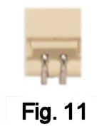
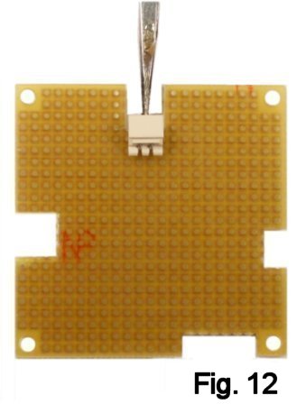
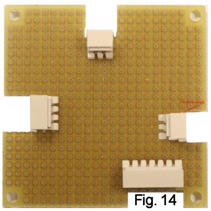
Power connector first--If you are following me, find a two-pin header as shown in fig. 11 and solder its pins in place at locations K-6 and L-6. I use locking tweezers as a "third-hand" when doing this. Use as little solder as needed to get a solid joint.
Pay close attention to the layout drawing when locating connectors and components, because mistakes will have you crying later when things don't fit...
Now for the first connection: This one connects the negative side of the power supply jack to the Ring contact of the input jack (Fig. 15). Beginners: This is how the ground connection for power is completed when you plug your guitar into the input jack. The barrel of the guitar plug shorts Ring to Sleeve.
Start by using the soldering iron to heat the pads at indexes I-5 and J-5 enough to remove them.
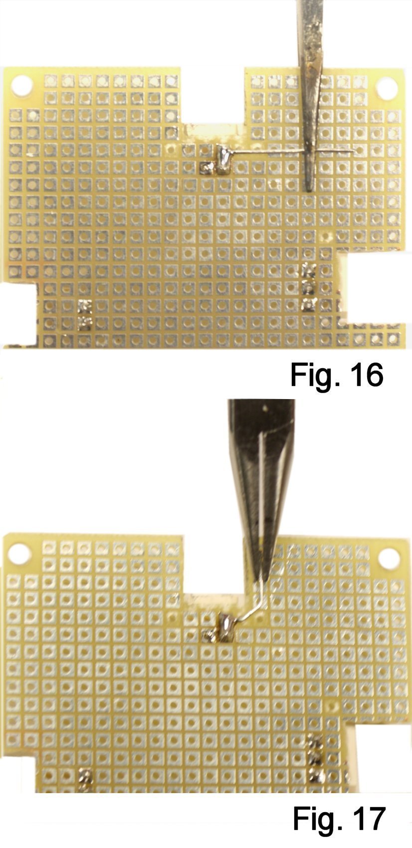
Cut a piece of bare wire about an inch long and use the locking tweezers to hold it at index K-5. Solder at K-5, and use just enough solder to "bridge" pads K-5 and K-6 (Fig. 16). Using chain-nose pliers, create a 45 degree band at J-5. Then do another bend to bring this conductor up into column I (Fig. 17). Trim any excess at I-1.
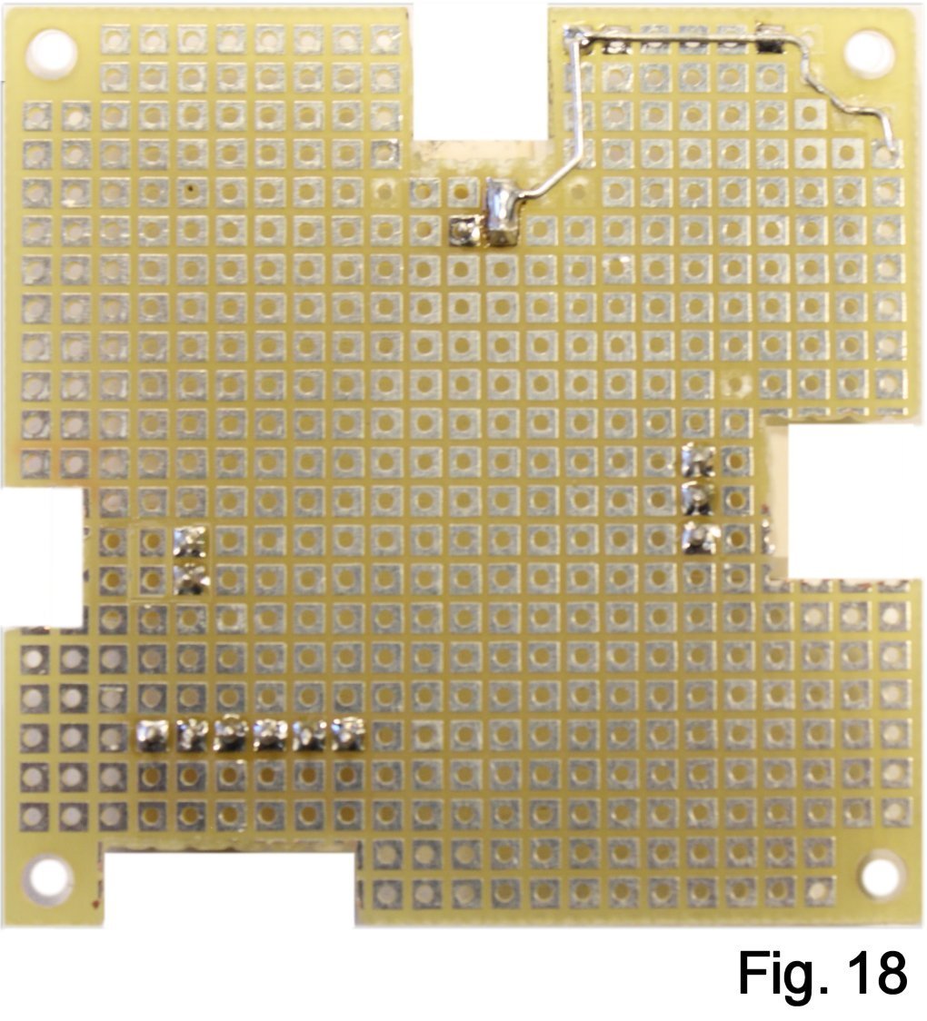
Cut a short length of wire, hold it in place at I-1 and solder at I-1 and D-1. Using the chain-nose plier, route the conductor carefully around the mounting hole. Bend downward in column A and trim any excess at A-4 (Fig. 18).
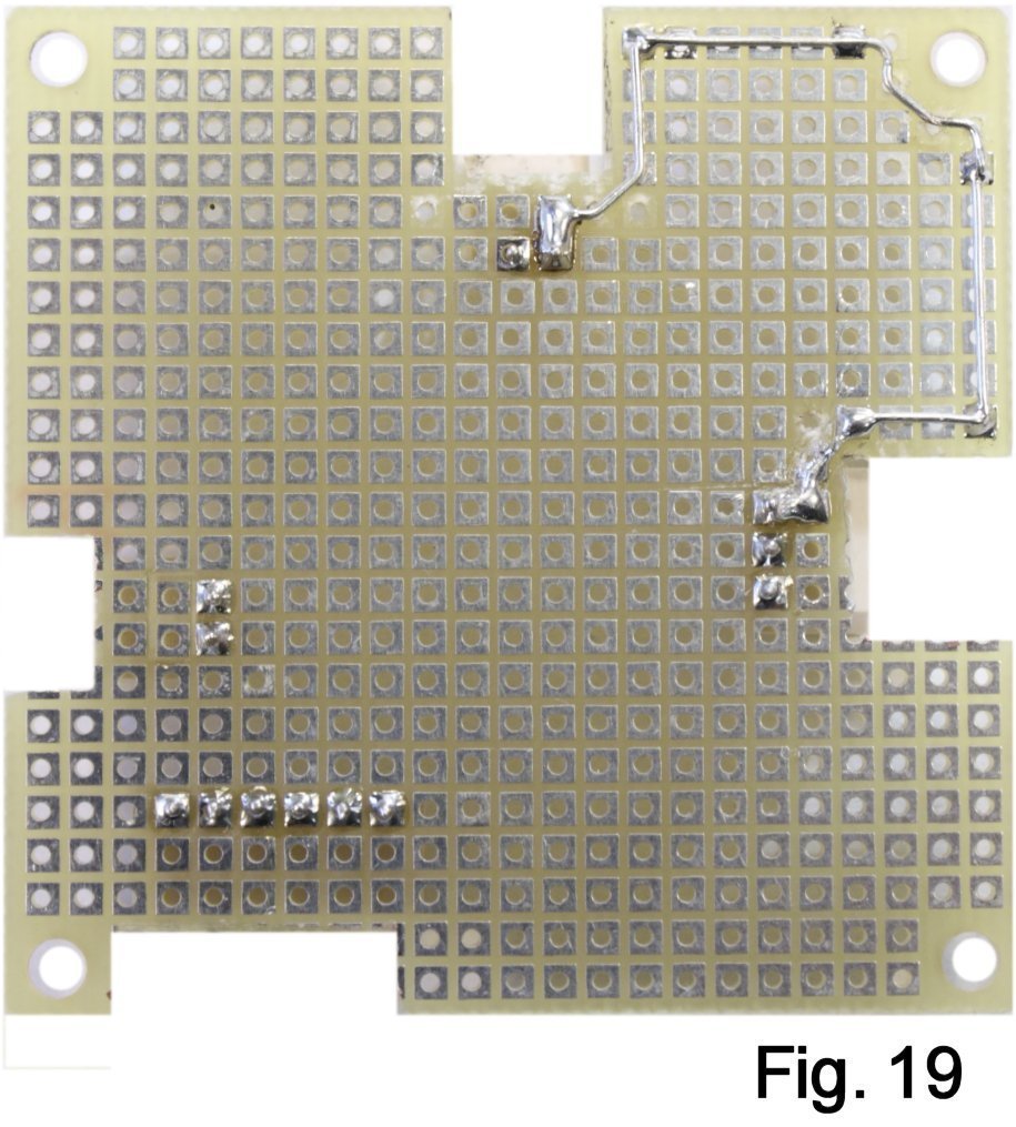
Continue the run to A-10, create a right-angle bend here and solder. Remove the pad at E-11, create a 45-degree bend at D-10, and finish the run by joining E-12 and F-12 (Fig. 19).
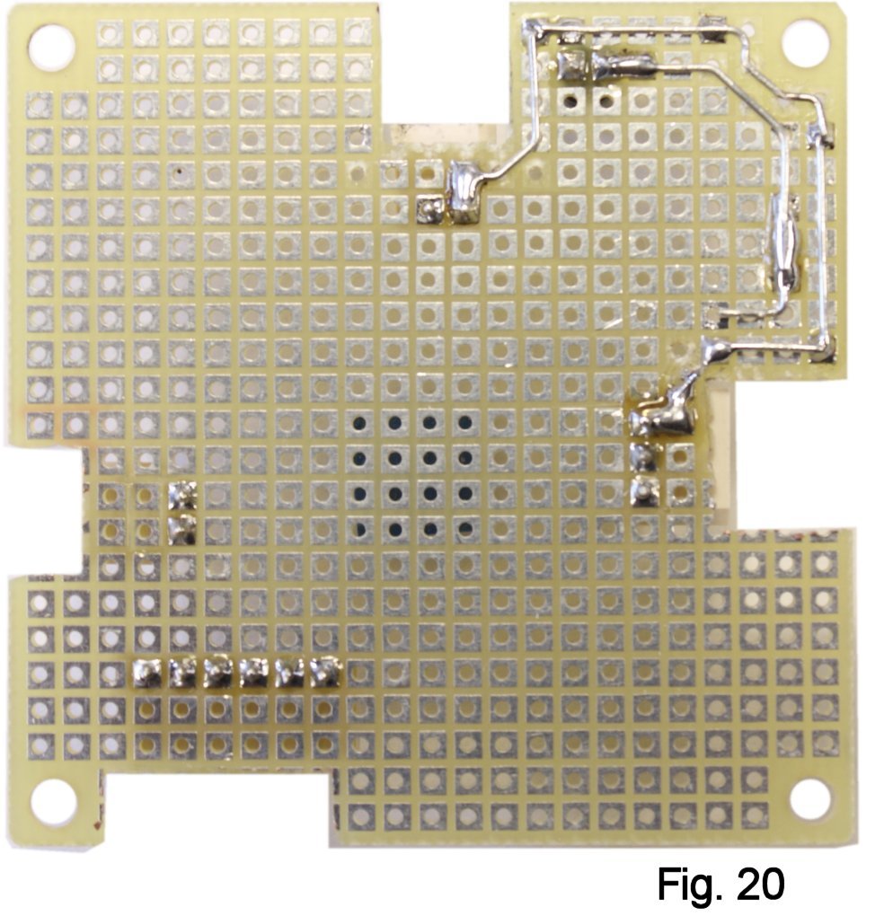
Cut a short length of wire, hold in place with tweezers and tack at G-2. Bend downward at D-2 and then right-angle downward again in column B. Continue the run to B-9, right-angle bend to D-9 and trim. (Fig. 20). It's a bit like creating PCB traces by hand...
I hope it's clear that I'm leaving a break in the ground bus to allow inserting one side of RS2 later; in a different build, the run might just continue on.
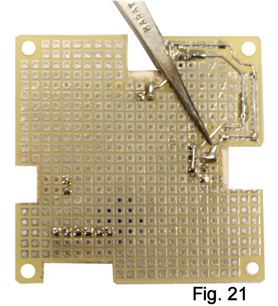
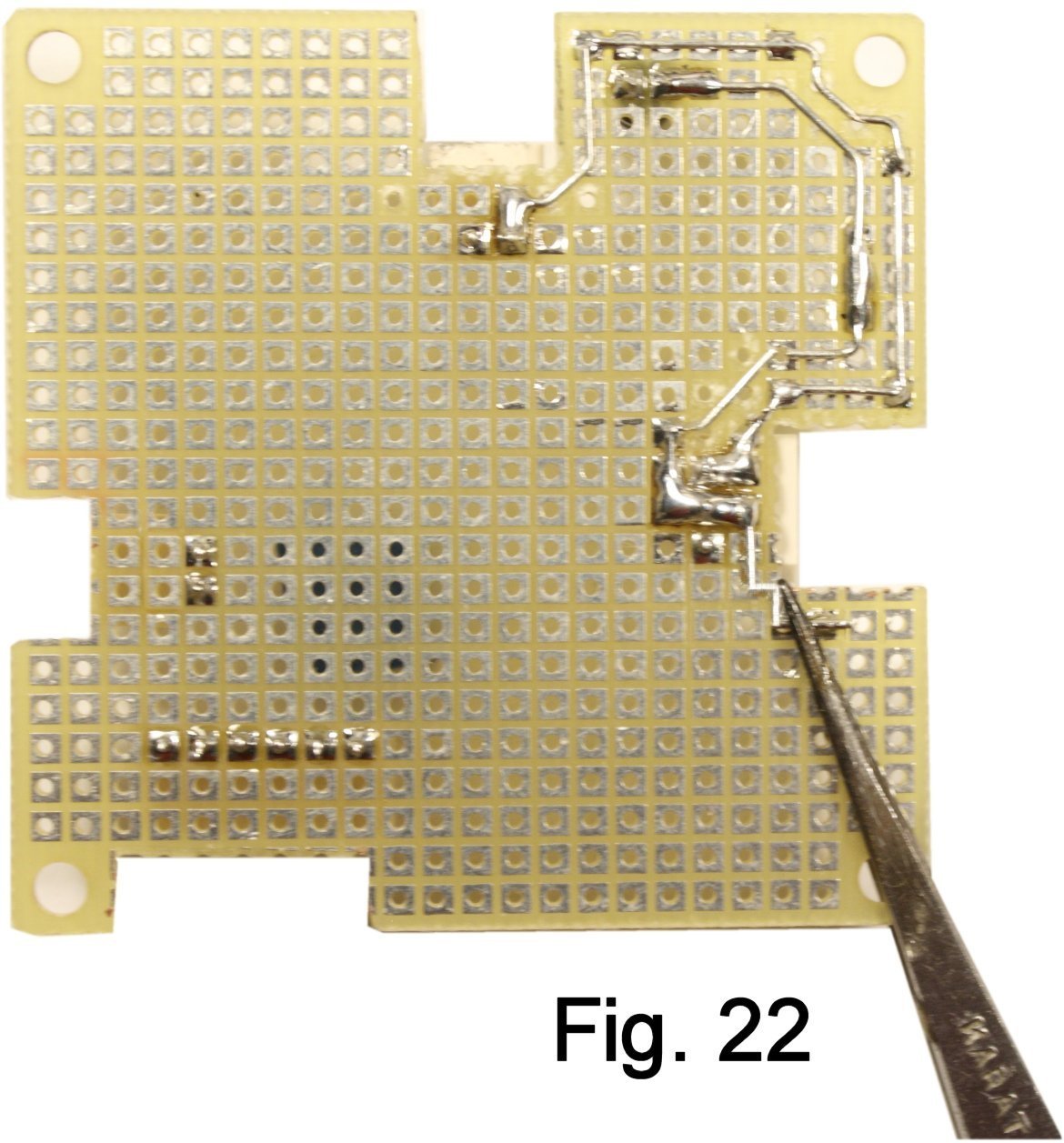
Remove the pads at D-10, E-10, E-11 and F-1 1. Cut a short length of wire, hold it in place starting at G-13 and tack there. Make a right-angle bend at G-11, then bend diagonally from index F-11 to the opposite side of pad D-9 (Fig. 21).
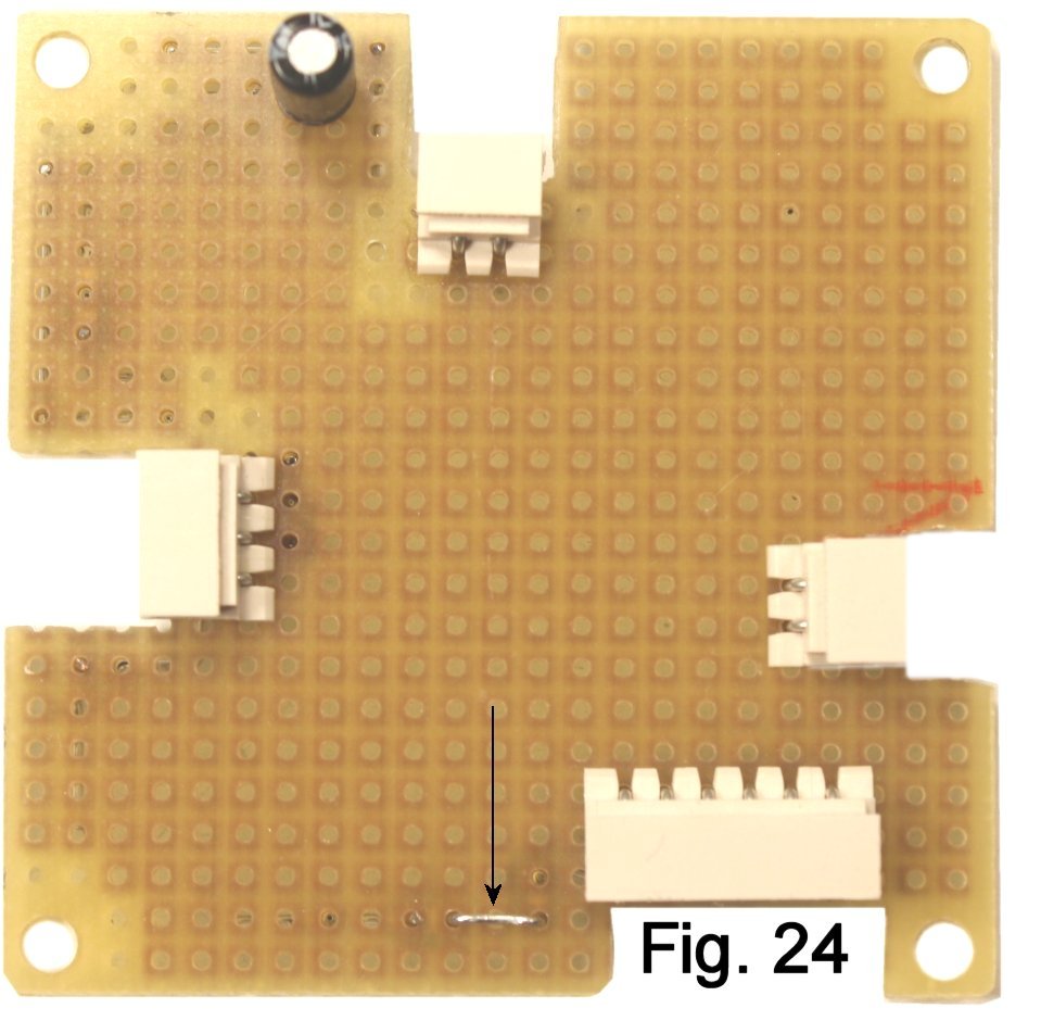
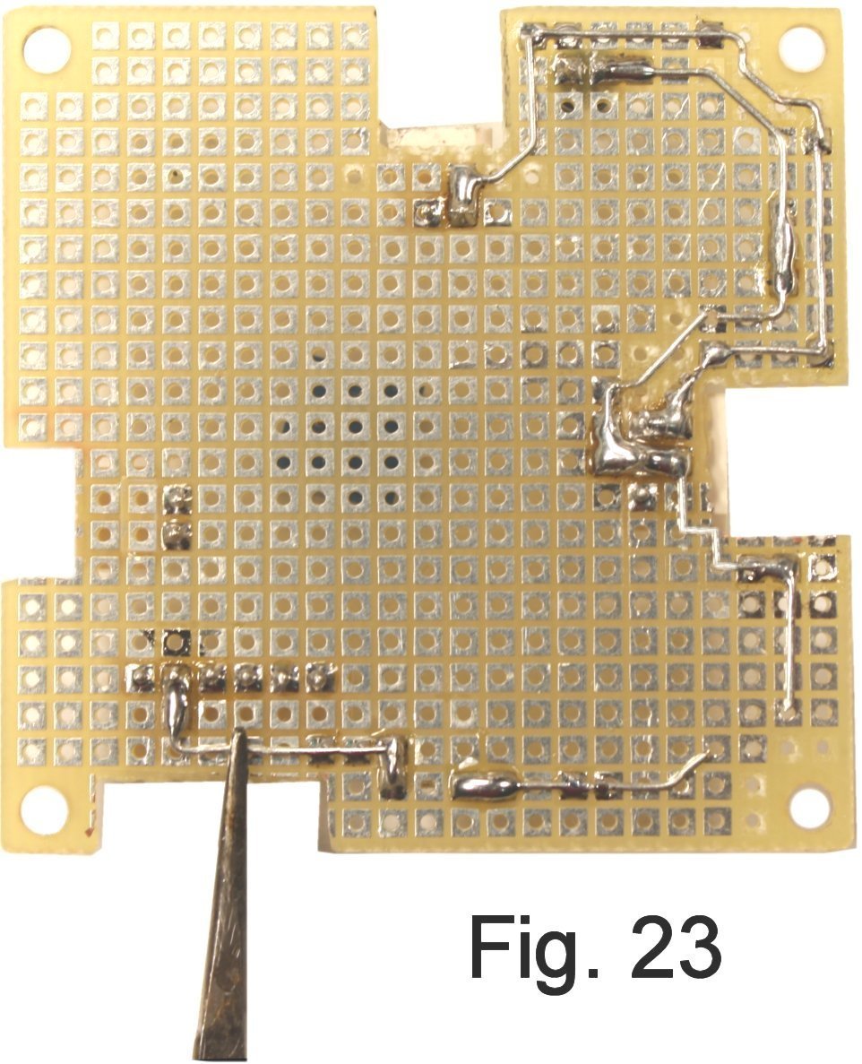
I found it easier to wire the next section by starting at pin 5 of the switch connector. Hold a short length of wire in place at pin 5 and solder. Do a right-angle bend in row 21, another right-angle bend down, stop at row 22 and trim. Now install a jumper on the top side that spans three holes, K-22 to M-22. Wire on the bottom from K-22 back to F-22, and leave enough wire at the end to bend upward to D-21 (Fig. 23 and Fig. 24).
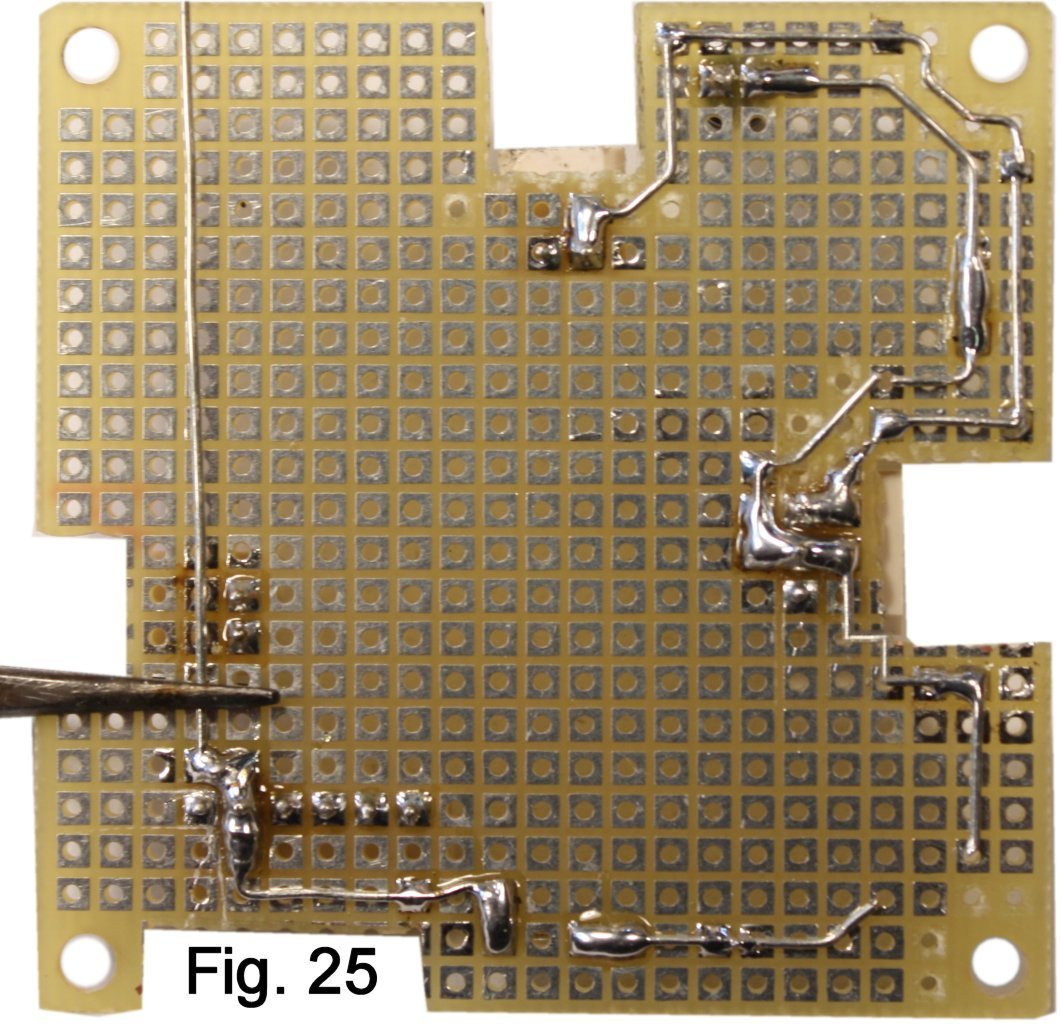
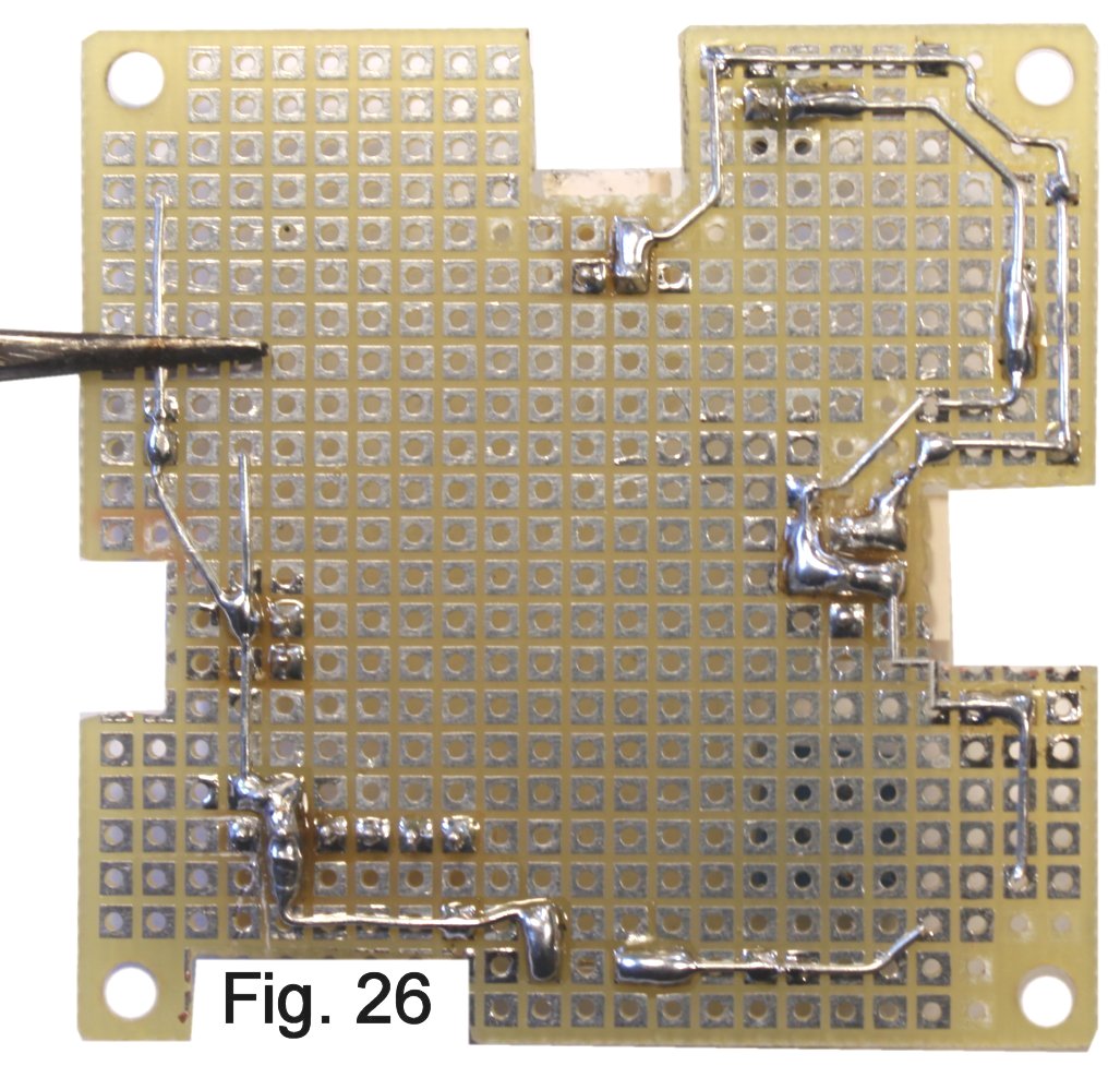
Cut this length off at pad T-10. Start a length of wire at index V-4, bring it down to V-12 and tack at V-10. Bend the end toward T-13, cut off there and solder to join. The ground bus is finished (Fig. 26).
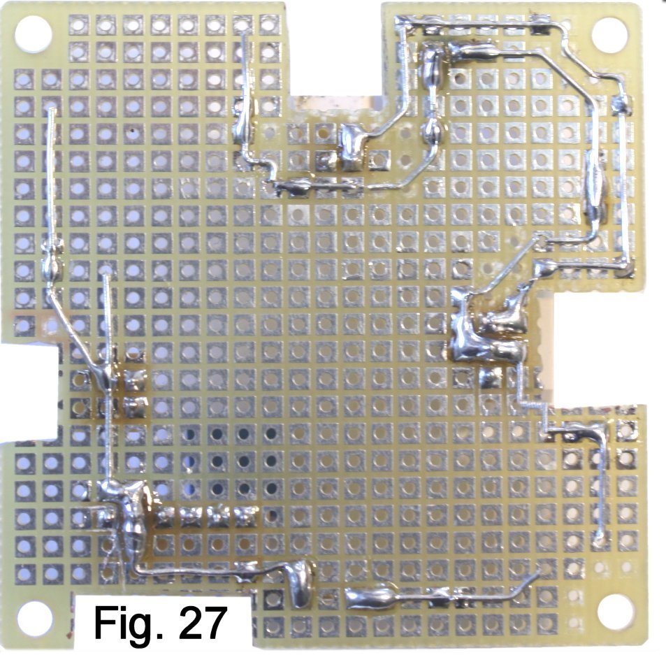
Join a length of wire to the positive side of capacitor C6 by adding solder. Tack at H-5, right-angle bend at H-6 and bend downward to row 7.Bend again to meet up at the point where the resistor enters at K-7 and trim (Figure 27). The positive power bus is done.
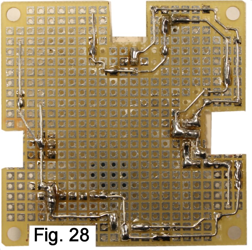
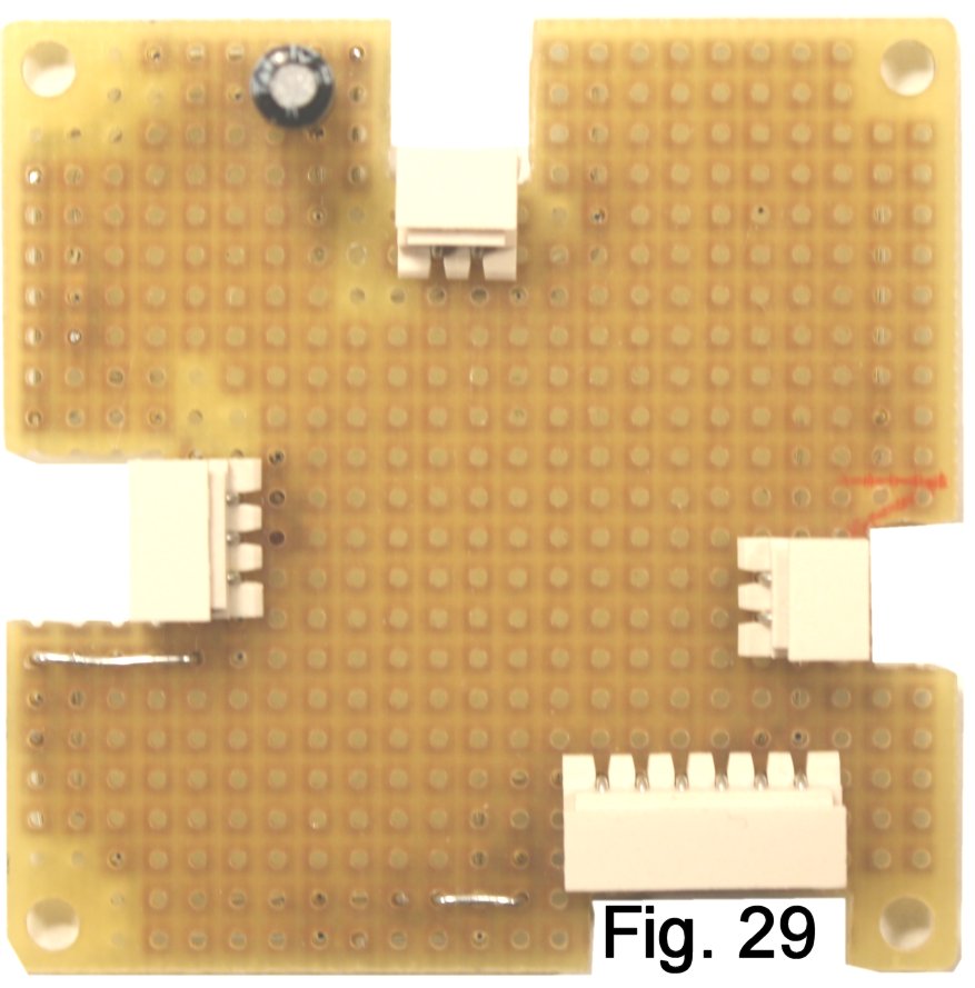
The connection to the Tip contact of the input jack requires a jumper from A-16 to E-16. If you leave enough wire on the end of the jumper that's closest to the Tip contact, it's easy to add a right-angle bend at F-16 and solder that connection.
From the opposite side of the jumper, run carefully around the mounting hole and then to L-23. From pin 1 of the switch connector, complete the run back to L-23 (Fig. 28, Fig. 29)
Install a jumper from O-17 to R-17, and leave enough wire at R-17 to bend over and meet pin 4 of the switch connector. This is the connection from the output of the effect to the stomp switch.
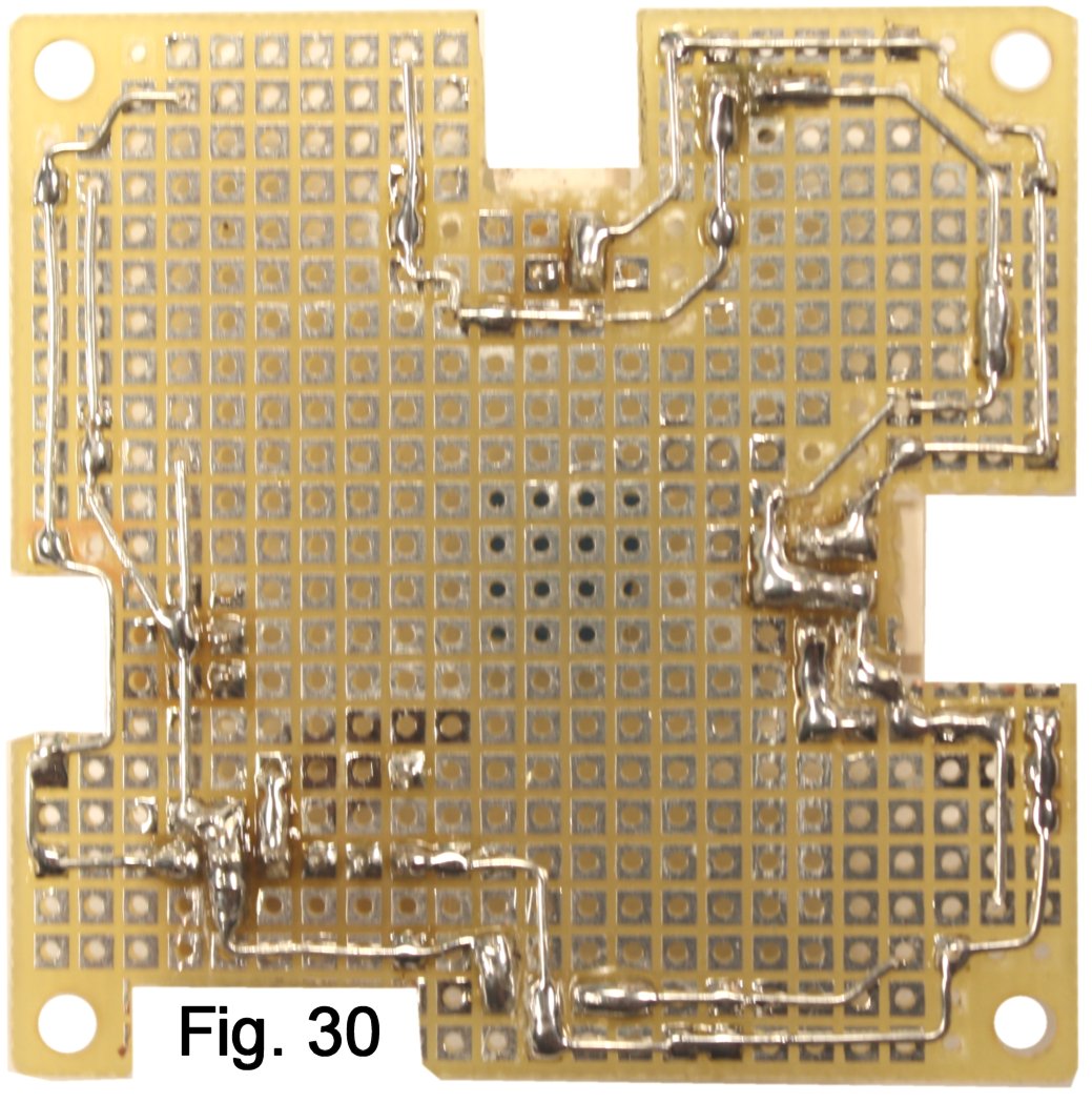
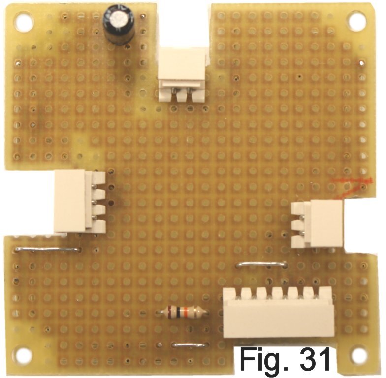
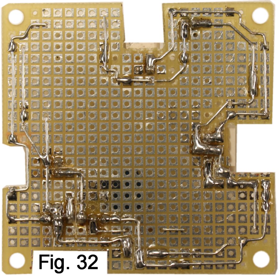
The last signal connection goes from pin 3 of the stomp switch connector to the output jack tip. Since I was working on the switch connector, I installed R1 and made its connection to pin 2. (Fig. 30, Fig. 31, Fig. 32).
We have created most of the "support" connections for the effect. Now we can continue to stuff the board with components and wire the effect itself. But first...
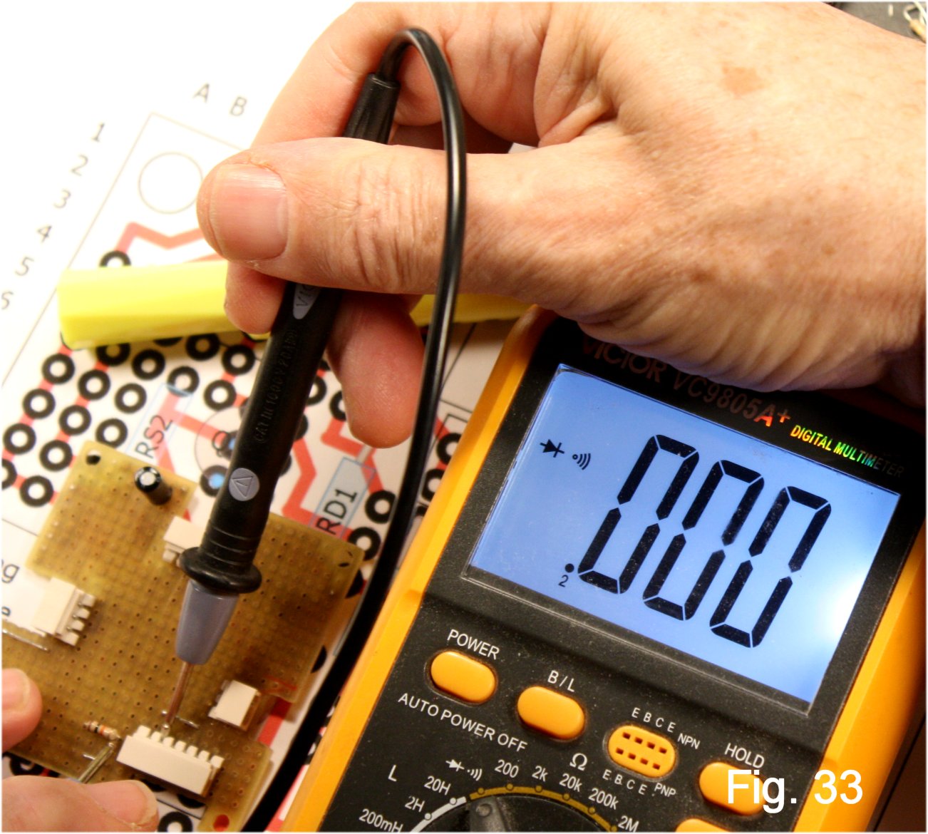
Print a clean copy of the layout drawing, Figure 3. Set your multimeter to its continuity scale and test from point-to-point. Make sure that every run is going to where it should, and that points that are supposed to be joined actually are. Mark off with a highlighter when done. This is the most important thing you can do to avoid frustration later (Fig. 33).
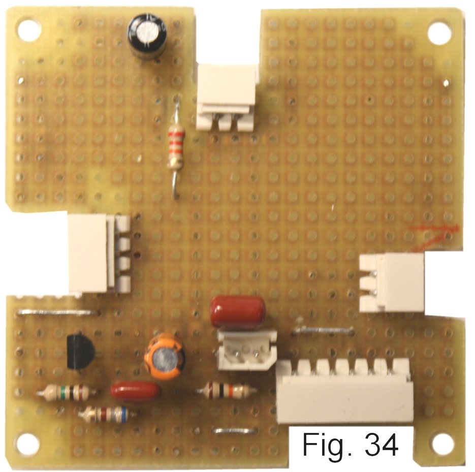
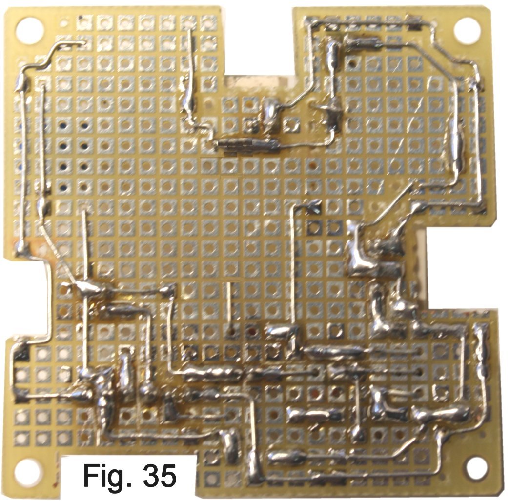
Stuff The First StagePay careful attention to orienting Q1 and CS1 correctly. The values of RS1 and RD1 will depend on the device being used for Q1. If you bought the breadboard kit, RD1 is calculated for the desired gain of the stage and the value for RS1 is noted on the bag. RD1 must span 6 holes! (Fig. 34, Fig. 35).
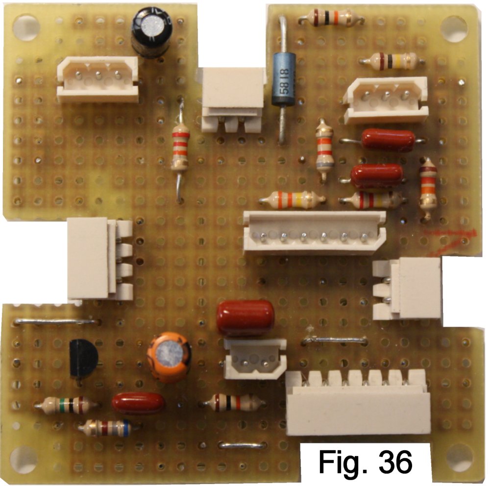
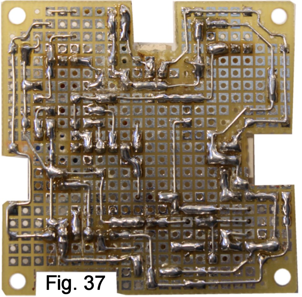
The leads of capacitor C4 must be formed to span four holes, and C5 spans five. The perfboard wiring here presumes that you'll be installing the equalization pad R7-R8. See the breadboard article for suggested resistor values. If you don't use it, leave out R7 and R8 and jumper pin 1 to pin 4 on the switch connector. While you are in this area of the board, install diode D1 to deliver power and R11 to drive the in-use LED. D1 spans seven holes. (Fig. 36, Fig. 37).
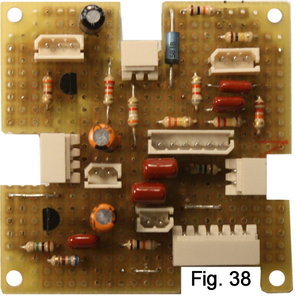
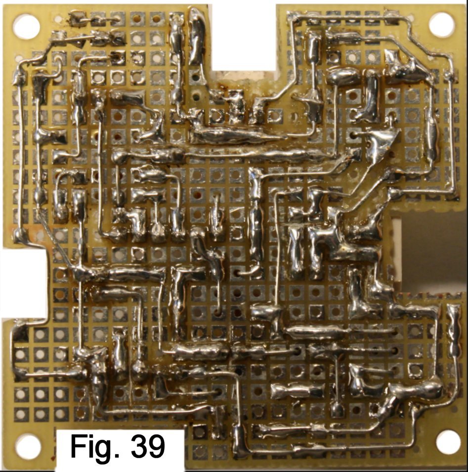
As in the first stage, pay careful attention to orienting Q2 and CS2 correctly. The values of RS2 and RD2 are also selected for Q2. RD2 must span 6 holes! (Fig. 38, Fig. 39).
The board is finished except for the in-use LED, and we'll connect that temporarily during initial testing. Before you proceed, do a thorough continuity test of all the wiring. If the wiring checks out, it is time to assemble the outboard components: pots, switches, signal and power connectors.
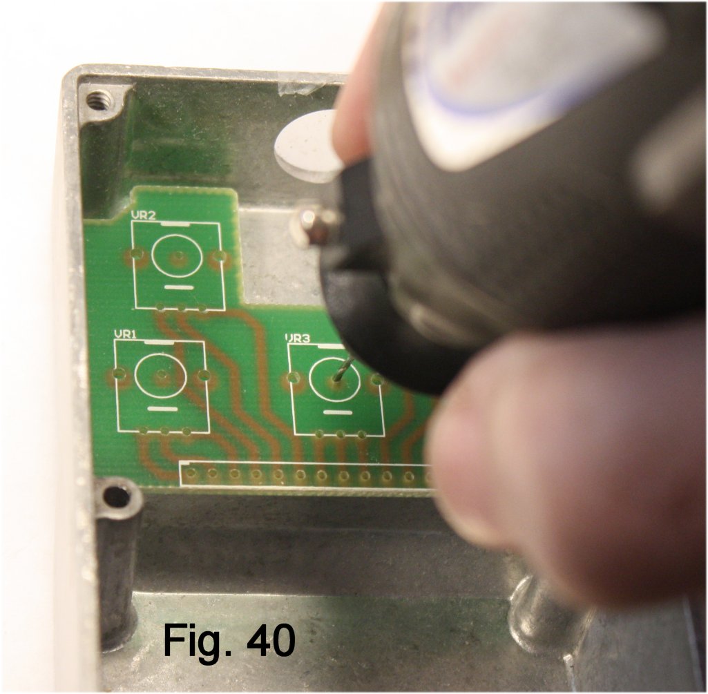
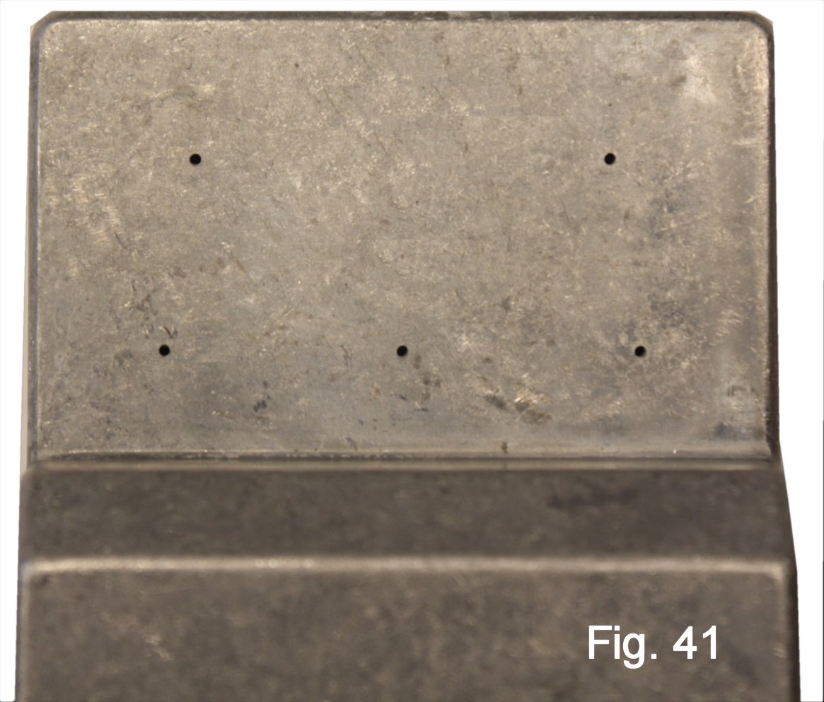
This part of the assembly raises some of the mechanical design and choice-ofcomponents issues that I have talked about in other "Breadboard-To-Box" articles: Because we will be mounting five controls, I choose to use 9mm right-angle pots; they make the mechanical layout less cramped. It's possible to install pots with solder terms and wire to the pins. However, for ease of assembly, I decided to hack up and re-wire a five-pots board so that all of the controls would drop into place at once.
Before doing any other tooling, I used the five-pots board board as a template to set the center positions of the holes for the controls (Fig. 40, Fig. 41).
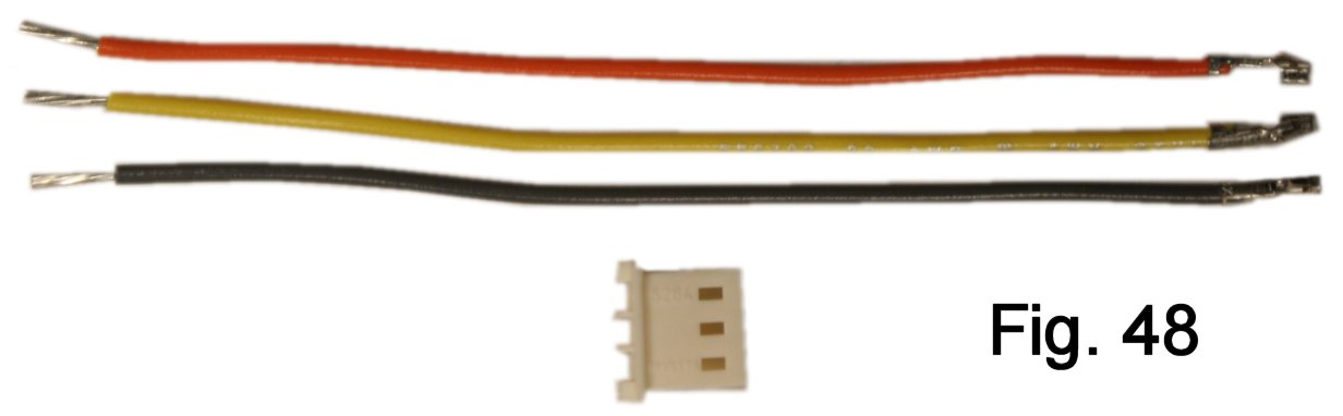
I presume here that you are using my modular approach to making the connections, so find three terminated leads and a male three-pin Molex housing (Fig. 48). Reserve the red and black leads for power. Other than that, it's your choice for which color goes where.
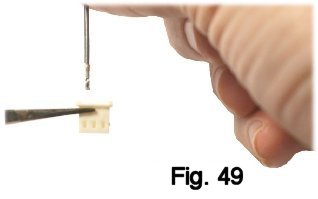
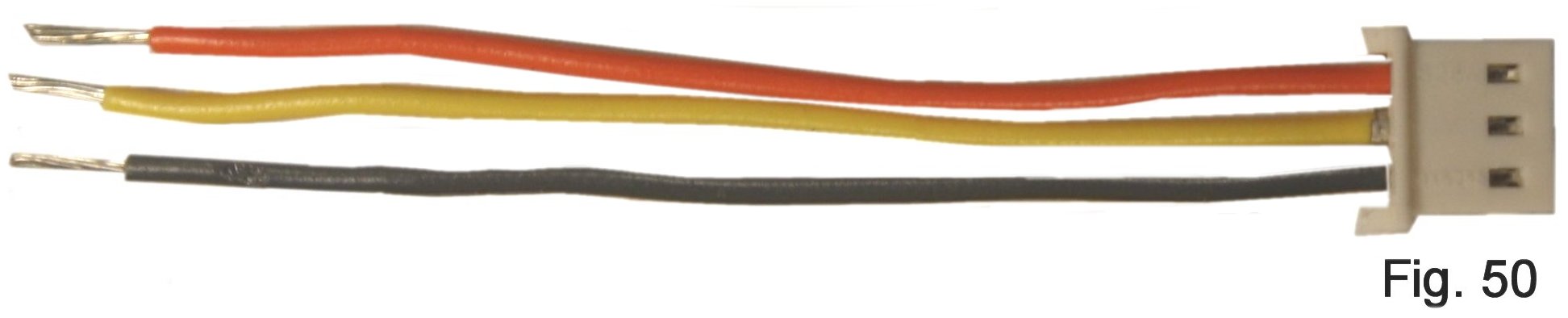
Install each lead into its hole in the housing. The terminal has a flange on one side, and you will feel it click into place when it is fully inserted Cut the leads down to about 2" and strip (Fig. 49, Fig. 50). This will be the connector for the level pot.
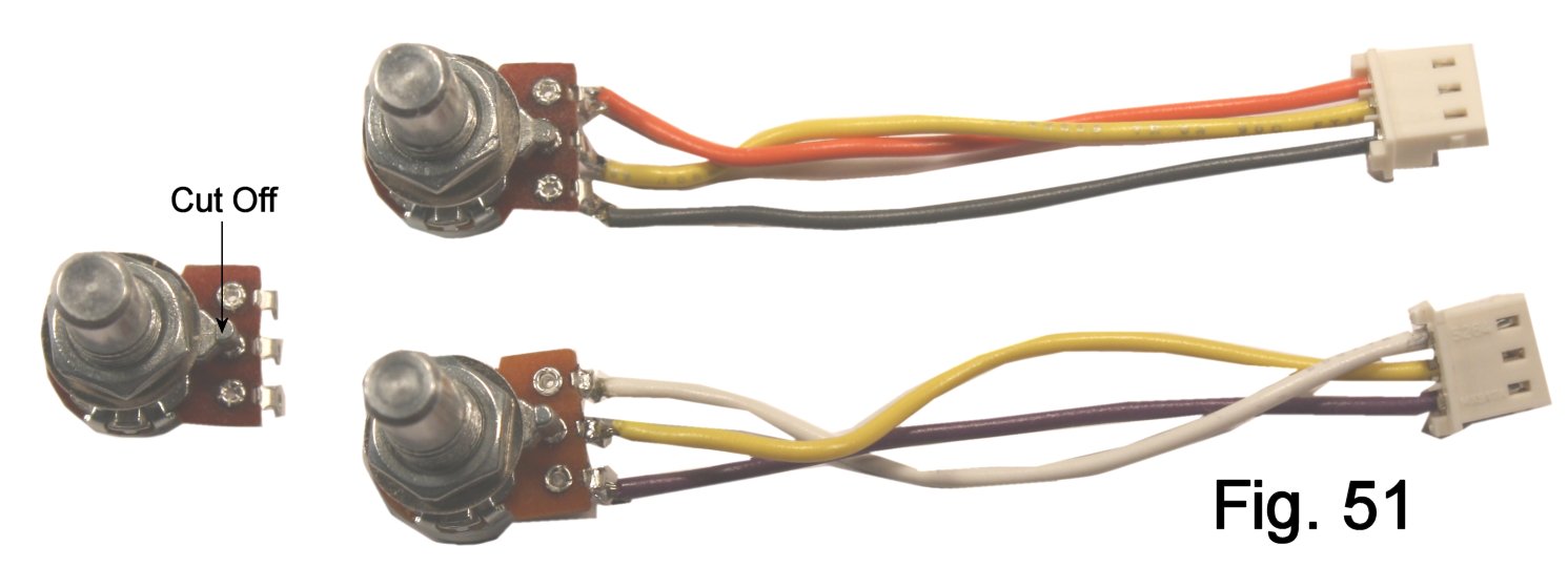
Make another connector in the same way, but color-coded differently, for the tone pot. Both of the pots have anti-rotation tabs that need to be broken off or cut off. Solder the connectors to the pots (Fig. 51).
Make two two-pin connectors for the toggle switches. These don't need to be color coded, since they are for non-polarized contact closures. Do leave their leads long so that they will have no problem reaching the appropriate headers.
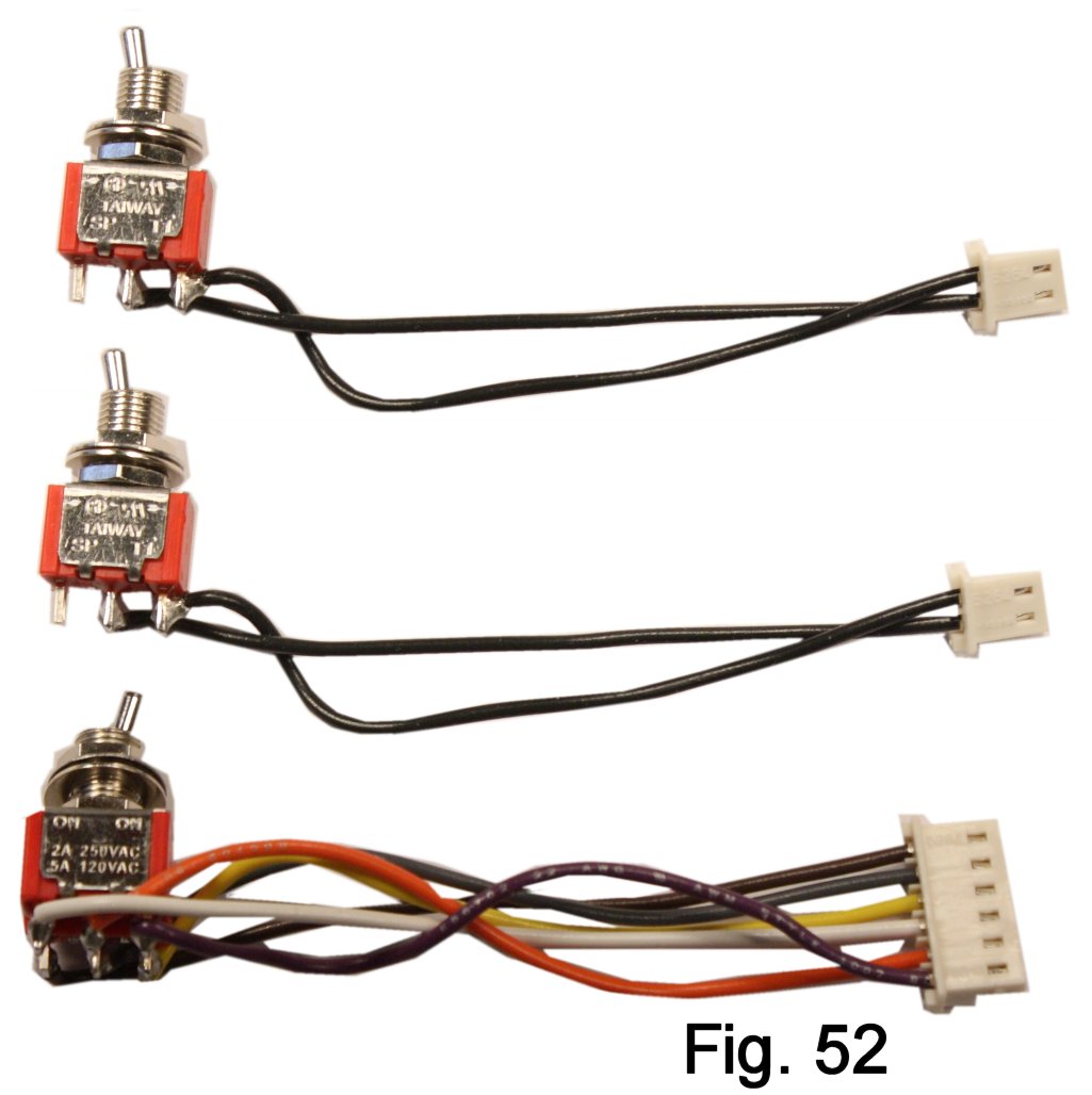
Make the six-pin connector for the Tone Bypass toggle switch. This one definitely needs to be color-coded, and the drawing shows which pin of the connector goes where. The designation "T1" is engraved on the side of the switch over one of the pins. Wiring as shown here will make the gain increase and the tone stack active when the switches are flipped upward (Fig. 52, Fig. 53).
We're not done yet! I know it seems like a lot of work. However, the modular base that we are creating makes the whole thing snap together later like Lego blocks.
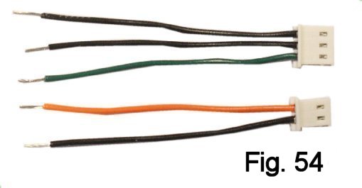
Find a two-pin and a three-pin Molex plug. Assemble the connectors for input and output, using black leads where shown in figure 54. While the other leads can be any color, you may want to follow my example to avoid confusion.
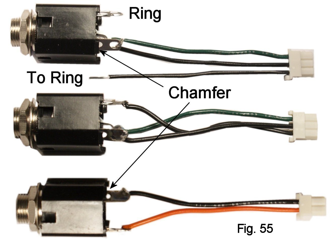
The Bare Box #1 enclosure is tooled to be friendly to shrouded jacks like those used in many "name" pedals. These have a chamfer on the sleeve pin edge, which is helpful for identifying the contacts. Start by locating the sleeve contact of the input jack and soldering the black center lead of the plug to this contact. The sleeve contact is the one on the beveled edge (“chamfer”) of the jack. For ease of assembly later, it’s best if the lead enters from the bottom of the contact and is bent at right-angles as shown before soldering (Fig. 55).
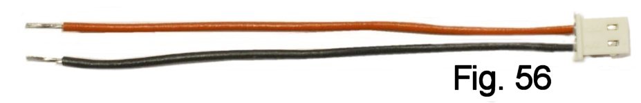
In the same way that you created the other connectors, install black and red leads to set up a two-pin connector for power (Fig. 56).
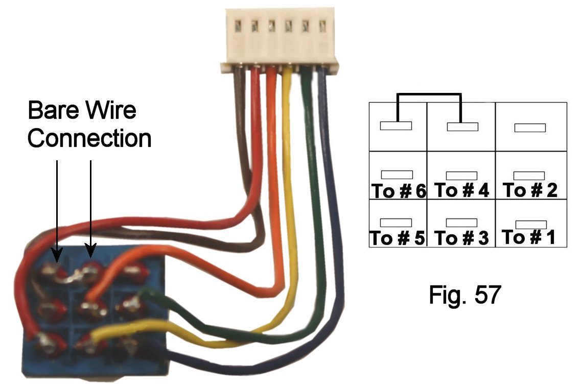
The last piece of pre-assembly before putting everything together is creating the connector for the stomp switch and soldering those components together.
Find the six-position Molex connector and the terminated leads for it, and assemble this as you did the others. While there is no standard for which color goes in which position, you may want to follow what I show in figure 57 for ease of troubleshooting.
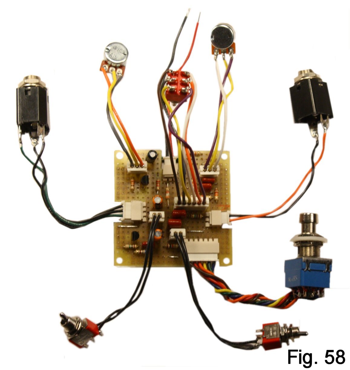
Are you ready to test your work? Plug in pots, jacks and stomp switch as shown in figure 58. Set the level pot about 1/4 clockwise and the tone pot to its mid-point. Connect your guitar and an amplifier and connect a battery to the power leads. If you don't hear a clear volume change, click the stomp switch. Make sure all the controls work. Got boost? CONGRATULATIONS! You can add the in-use LED and then proceed to the section on finishing the enclosure.
If your build doesn't work, don't be too discouraged. Take a shower and grab a bite, since we know that you haven't done either one since you started this thing; troubleshooting requires a clear head and normal blood-sugar level. The first rule to keep in mind is that projects like this are all-or-nothing. If EVERYTHING is correct, the build works; if ONE thing is wrong, it doesn't. But you have something going for you: I built from the drawings and pics shown here, and you can rely on them. Use them as your bible, and you'll find out what's wrong.
To start troubleshooting, make clean copies of both the schematic and the layout drawing. Use a highlighter to mark off connections as you check them. Go over the off-board connections first. If those look good, you have to verify the interconnections. Use the continuity setting of your multimeter to make sure that you actually have a connection between every point in the layout that is supposed to be connected, and that nothing is shorted. Found a bug? Time to do repairs.
You can also use the low-voltage scale of your meter to sniff out problems. With your guitar plugged into J1 (necessary so that the battery circuit is complete), hang the negative lead on the sleeve of the input jack. Go back to the breadboarding article, measure the voltages at Gate, Drain and Source of Q1 and Q2 and compare with what the correct voltages should be for your devices. Any serious differences will give you an idea of where to fish for problems.
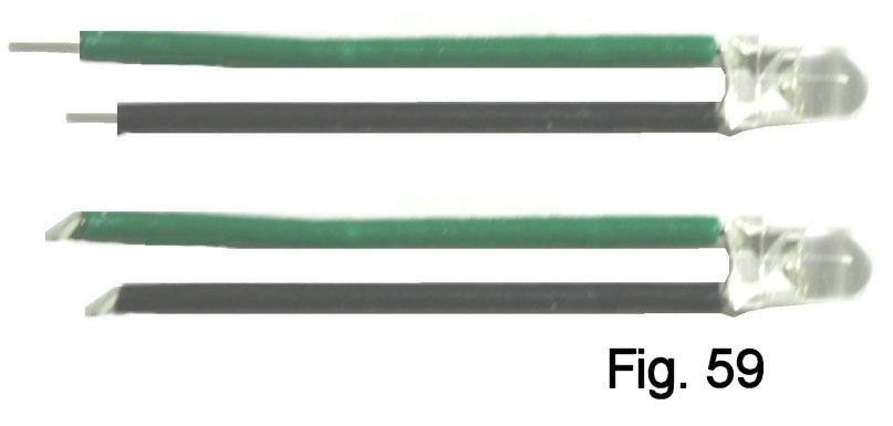
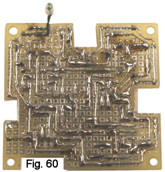
Once you have the effect working, the LED can be added. It's a diode, and so is polarized. By convention, LEDs are supplied with the negative lead shorter than the positive. Insulate the leads using short pieces of spaghetti tubing, and then put right angle bends at the ends (Fig. 59).
Solder the leads to the pads on the underside of the board. Positive goes to S-1 and negative to S-2 (Fig. 60).
Before you go further, re-assemble your test setup and make sure that the LED works properly. If it does, the board is finished.
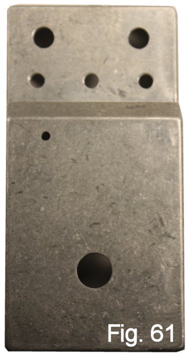
Before you paint and decorate, finish boring the holes for the switches and pots and add one for the in-use LED. The location for the LED hole can be eyeballed, because bending its leads slightly will allow it to be inserted slightly left or right. Once all the drilling is done, make sure that the LED eases into place (Fig. 61).
All the finishing methods I am familiar with begin with sanding to produce a smooth finish that will be friendly to paint, powder-coating and/or decals. I like to wet-sand starting with 220 grit Carborundum paper, and I use progressively finer grits up to 600 to get a finish suitable for taking paint or decals. You can get ideas and techniques for decorating and labelling from many on-line sources as well as some of the other project articles at SBE.
Once the enclosure is decorated, you want to keep it from accidentally being dinged while you work. Put a soft cloth down on your work surface to protect the face, and Move Slowly, especially when you have a tool in your hands (long experience!).
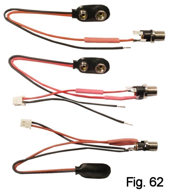
The next step is to wire and install the DC power jack, the male power connector and the battery snap. Begin by slipping a ¾” length of heat-shrink tubing onto the positive battery snap lead. Crimp the lead to the terminal on the jack, solder, and then conform the tubing to the connection using the side of your soldering iron.
In a similar way, attach the positive power connector lead. The negative leads for the battery snap and the power connector go to the ground terminal, and no insulation is needed (Fig. 62).
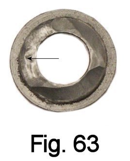
Before installing the assembly, thin down the shoulders of the insulating washers so that they will allow the washers to “grab” properly and not let the jack rotate. This can be done with sandpaper, or a grinding stone on a Dremel tool is ideal, if you have one (Fig. 63).
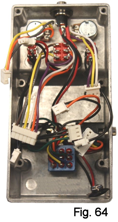
Mount the input and output jacks, dressing the leads as shown to keep their connectors out of the way of the stomp switch. Mount the stomp switch, being sure to orient it so that the connector is on the right. The battery snap leads go between the jacks and around the right side of the stomp switch. (Fig. 64).
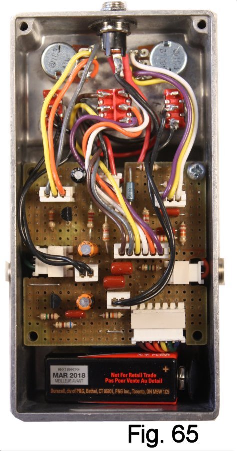
Move the plugs aside enough to ease the board into place. Plug in all of the connectors. Maneuver the LED into its mounting hole and set the board down on its standoffs. Install one of the round-head screws to hold the board down temporarily (Fig. 65).
Connect a battery and test the pedal. If something does not work, first make sure that all of the plugs are fully inserted and that none of the pins on the wires have worked loose.
If everything works, finish securing the board. The threaded studs secure the side of the board that is next to the battery, and two of the screws that secure the lid will screw into them. To complete the job:
- Secure the lid
- Stuff a small piece of foam padding over the battery
- Install the battery cover
- Install knobs
- Install rubber feet