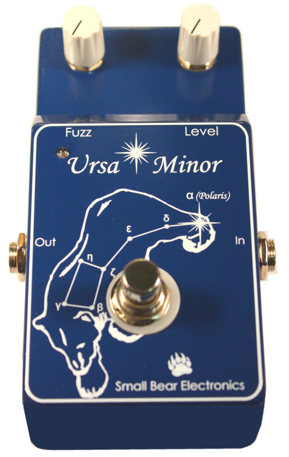
A note to builders who are "rolling-their-own" for technical or economic reasons:
I designed this build around my Bare Box #1, because it eliminates the risk of "stomped pots" that's common to most DIY pedal builds. However, if you have some experience or some help, you can adapt the ideas shown here to building in a standard enclosure.
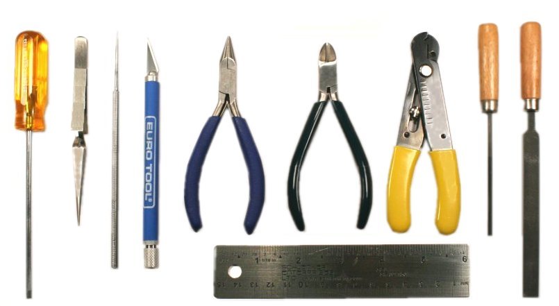
Before you begin, make sure that you have all the tools you need. You'll need a few basics:
- 25- to 35-watt soldering iron, rosin-core solder and cleaning sponge
- Small screwdriver(s)
- Small chain-nose pliers and side-cutters
- Small locking-grip ("Vise-grip") plier
- X-acto knife
- Self-locking tweezers or other "third hand"
- Small alligator clip
- Colored pencil or "Hi-liter" felt-tip marker
- Some small round and flat files
- A pointed steel "pick" or scratch awl
- De-soldering braid
These tools, and many others, are available in my Stock List.
If you are finishing the enclosure you'll need:
- 220-grit and 400- (or finer) grit carborundum paper
- Acetone, denatured alcohol
- Spray primer and enamel
- Decal stock or decals
- Clear lacquer like Krylon
| How Many? |
Description |
SBE SKU |
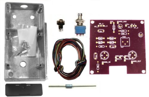
| 1 | Bare Box #1 - 2-Knob, Pre-drilled | 0350F |
| 1 | Schottky Diode 1N5818 | 2215A |
| 1 | High-brightness Red LED 3mm | 2304 |
| 1 | DC Power Jack - Long Bushing | 0612D |
| 1 | 3PDT stomp switch | 0200 |
| 2 | Knobs for 1/4" shaft | Your Choice |
| 1 | Stranded Hookup Wire | 0508B1 or similar |
| 1 | Printed Circuit Board | 0006B2 |
The enclosure on the right, SKU 0350F, is fully drilled but not
finished. If you would like the finished enclosure with the Bear, order SKU
0350G.
I will not go into detail here about how to solder. If this is your first build, you may want to check out an on-line tutorial and practice on scrap board before proceeding. Heat up and tin your soldering iron, wet your cleaning sponge and let's begin.
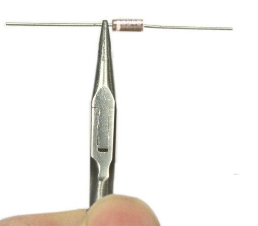
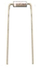
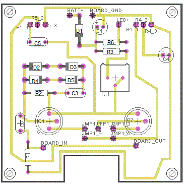
First up is the 1N5818 Schottky diode. Using a chain-nose plier, grab one lead of the diode about 1/16” from the body. Bend the lead sharply downward at right angles to the body of the component. Then do the same with the other lead. Refer to the silkscreened outline on the PC board, and be sure to orient the bar on the diode body correctly before installing the diode in its holes. Hold in place with self-locking tweezers, solder and trim leads on the bottom.
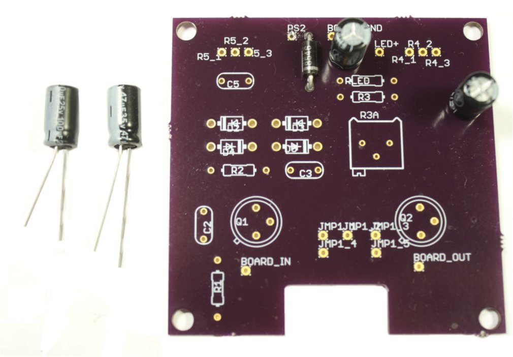
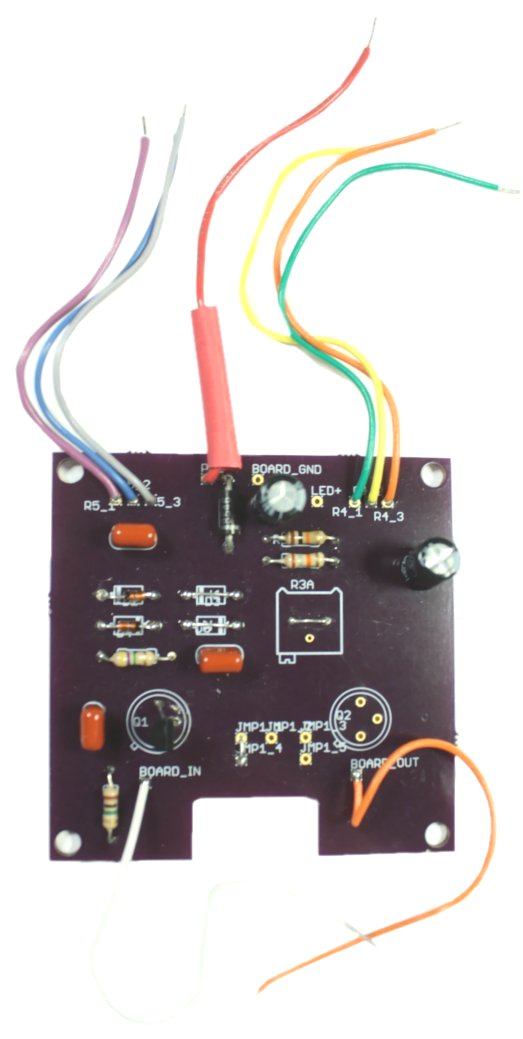
Resistor R_LED on the top right is 10K (Brown, Black, Orange, Gold) for the 3mm LED in the list above. Resistor R1 at lower left is 1 Meg (Brown, Black Green, Gold. Form the leads of these as you did the diode, install and solder.
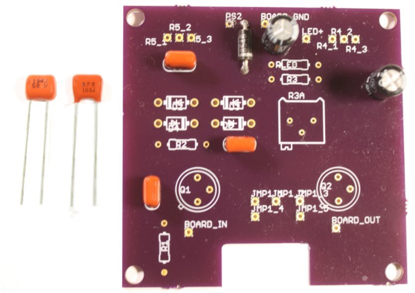
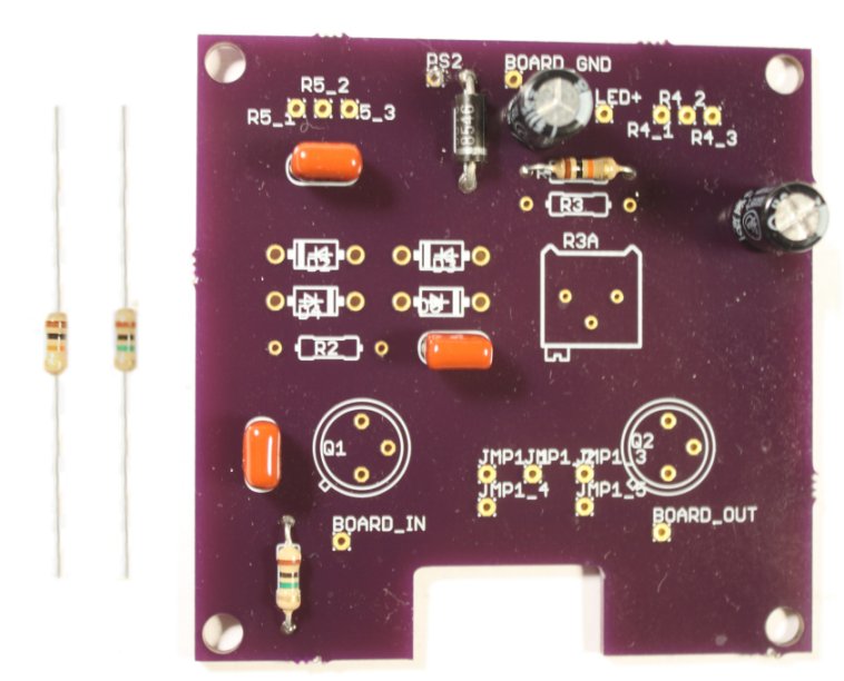
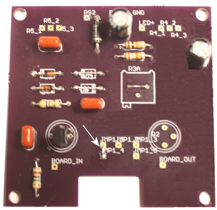
I mentioned earlier that several builds are possible on this board. This is the basic build: one 2N5089 transistor, two 1N914 diodes, a 4.7 Meg (Yellow, Violet, Green, Gold) resistor for R2, a pre-selected resistor for R3, no trimpot. Install the resistors first, and then solder a bare wire jumper between the pins of the trimpot.
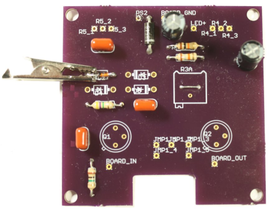
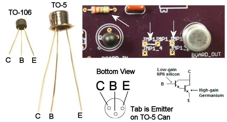
Modern silicon transistors and diodes will tolerate normal soldering heat without special precautions. Still, it's good practice to use an alligator clip as a heat sink, clamping this on each lead before soldering. Install the diodes, paying attention to orienting the black bar on the case with the silkscreened outline.
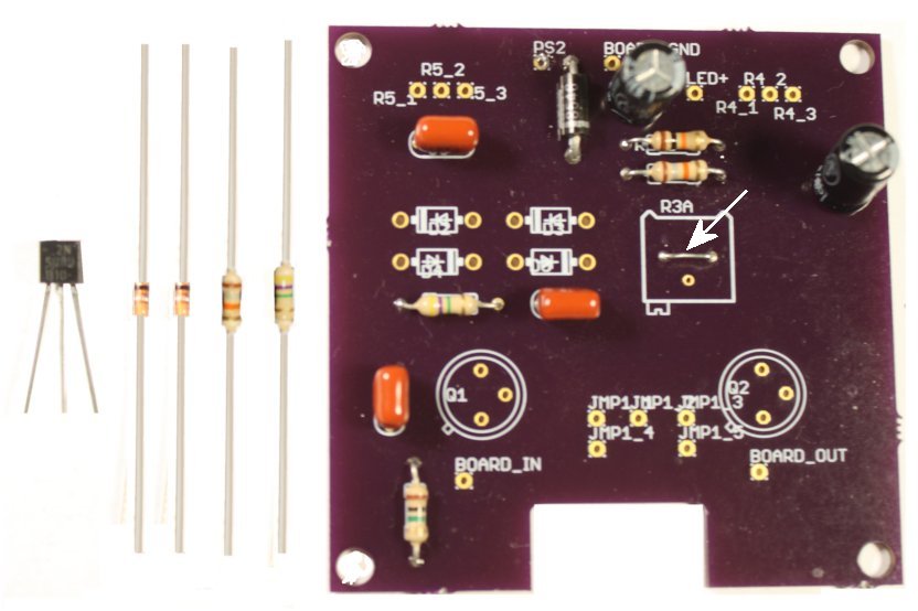
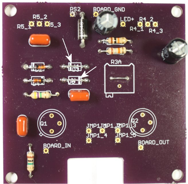
Solder two jumpers where diodes are not installed.
The transistor goes in with its flat side facing toward the outline for Q2. Jumpers are used to select the one- or two-transistor configuration. Since the basic build uses only one transistor, configure for that by installing a jumper as shown.
All of the components for the basic build are now installed. If you have an unfinished enclosure, this is the time to decorate it. Once the enclosure is ready, you can proceed to wire and assemble.
I strongly recommend trying out these mods on the breadboard before committing them to solder. Each one will have a different effect on the timbre of the pedal, and it's important to know what you want to wind up with. Take notes while you experiment and stuff the board accordingly.
- Clean Boost - To get this, just leave out C3 and the diodes.
- Biasing With A Trimpot - Install the trimpot rather than jumpering it out. You can leave R3 in place or jumper it out, If left in, its value can be determined by experiment; it depends on the range of control that you want. This circuit is famous for being almost infinitely configurable.
- Transistor Types/Darlington Pairs - If you install the Darlington pair, pay attention to getting Collector, Base and Emitter of both devices oriented correctly and jumper as shown. To get the range of control of bias voltage that I wanted, I reduced R2 to 2.2 meg.
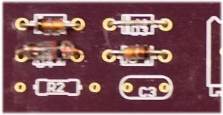
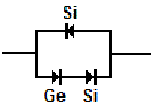
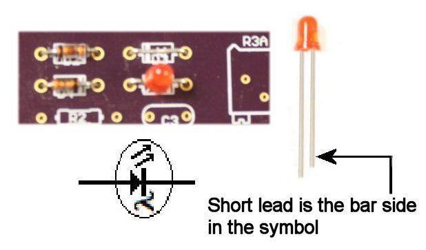
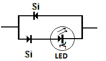
- Diode Types, Single or Series - The board can accommodate single silicon diodes back-to-back as in the basic build, or numerous combinations of diodes and LEDs both single and series-connected. If you install germanium, heat-sinking before you solder is a Must. If you use LEDs, make sure that you can ID cathode and anode. Typically, the short lead on those is the cathode (bar in the symbol). Examples:
In all cases, observe polarity of the devices! Now that the board is stuffed, you are ready to decorate the enclosure if that's not already done.
Since you are working with a decorated enclosure, start by putting down a soft, clean cloth on your work surface to protect the face.
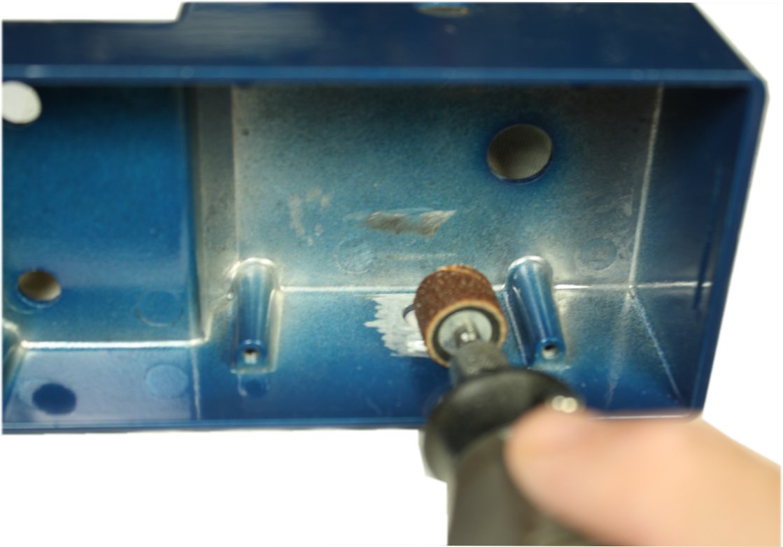
If the enclosure has paint or powder coating on the inside, give the area around the input and output jacks a thorough scraping so that the sleeves of the jacks have a positive ground connection. Also sand around the hole for the LED, since we will be using epoxy cement later to hold that component in place. The scraping can be done with sandpaper, but a sanding drum on a Dremel tool, if you have one, is much more efficient.
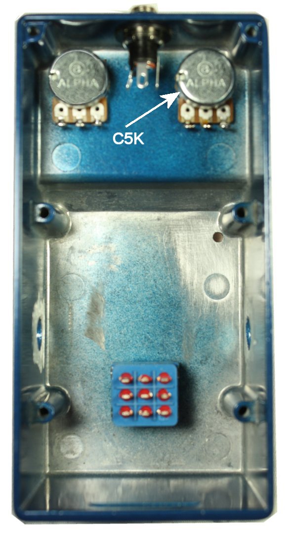
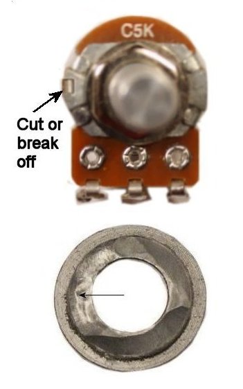
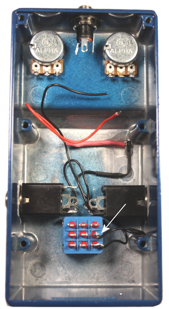
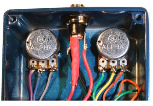
- Make sure that the fuzz pot (C5K) goes on the right. Both of the pots have an anti-rotation tab that needs to be removed before mounting.
- Orient the contacts of the stomp switch horizontally.
- I prefer the appearance of the long-bushing metal power jack SKU 0612D, but some builders will prefer a cheaper plastic one. The hole for the power jack will accommodate either. The shoulder washers for the metal version need to be sanded down a little so that they "grab" properly.
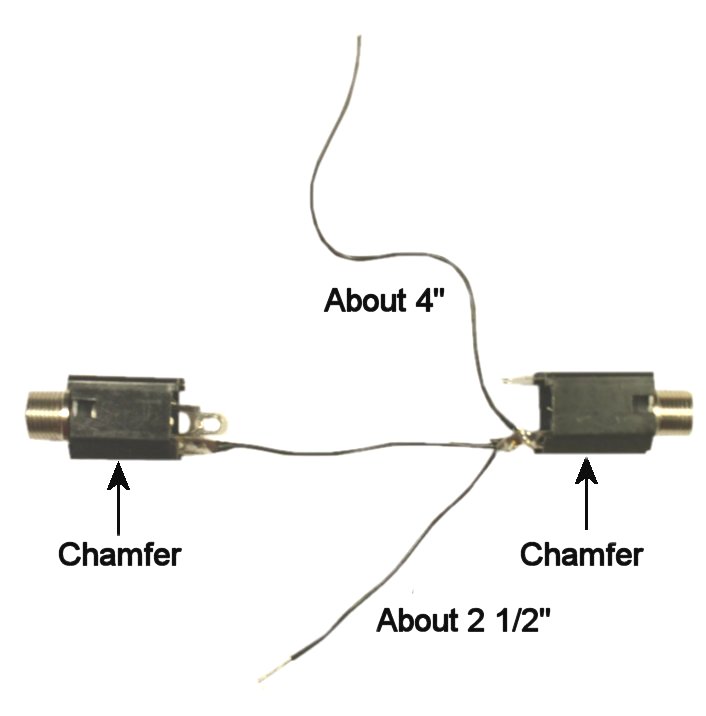
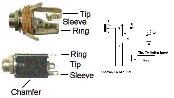
- Place the stereo jack (it has three contacts) on the left, mono on the right. Connect them with about a 2" lemgth of hookup wire and solder on the stereo side.
- Add two leads as shown on the mono side and solder.
- Install the jacks. The chamfered sides go closest to the enclosure floor. See why we did the soldering first?
- The short lead is soldered to the lower rightmost contact of the stomp switch. The longer lead will connect to the board later.
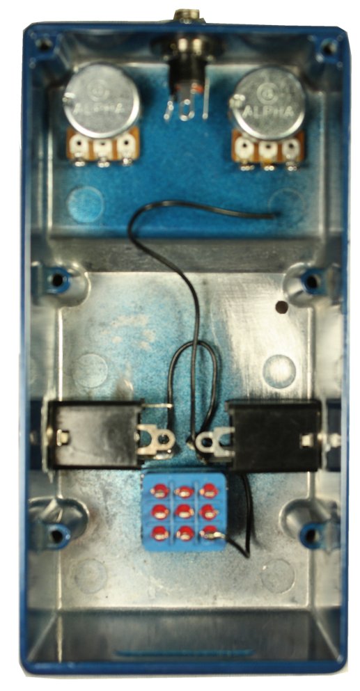
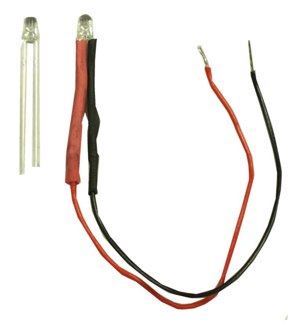
- Prepare it by soldering 3" of hookup wire to each lead and covering with heat shrink. I used black for the (shorter) negative lead and red for positive.
- Clean up the scraped area around its hole with a Q-Tip soaked in alcohol.
- When the hole is clean and dry, insert the LED with its negative lead on the right.
- Route the leads as shown in the pic. The negative lead goes under the sleeve contact of the output jack and is soldered to the middle contact of the right-hand column of the stomp switch.
- Mix a very small volume of clear, quick-setting epoxy cement, apply around the base of the LED and give it time to cure.
Wire the tip contacts of the input and output jacks to the stomp switch. I suggest using different colors of wire for this to make tracing easier.
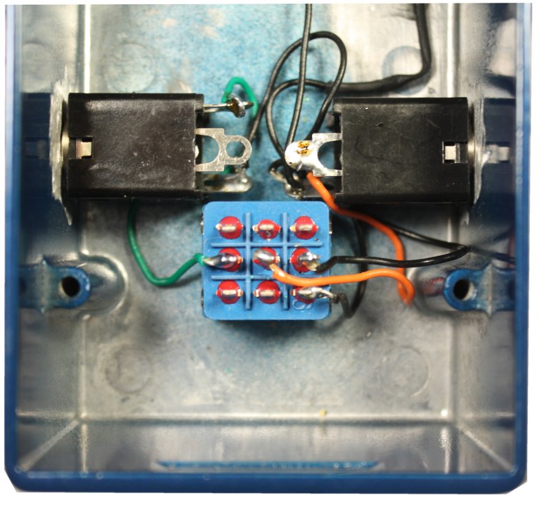
Route the battery snap leads on the floor of the enclosure past the right side of the stomp switch.
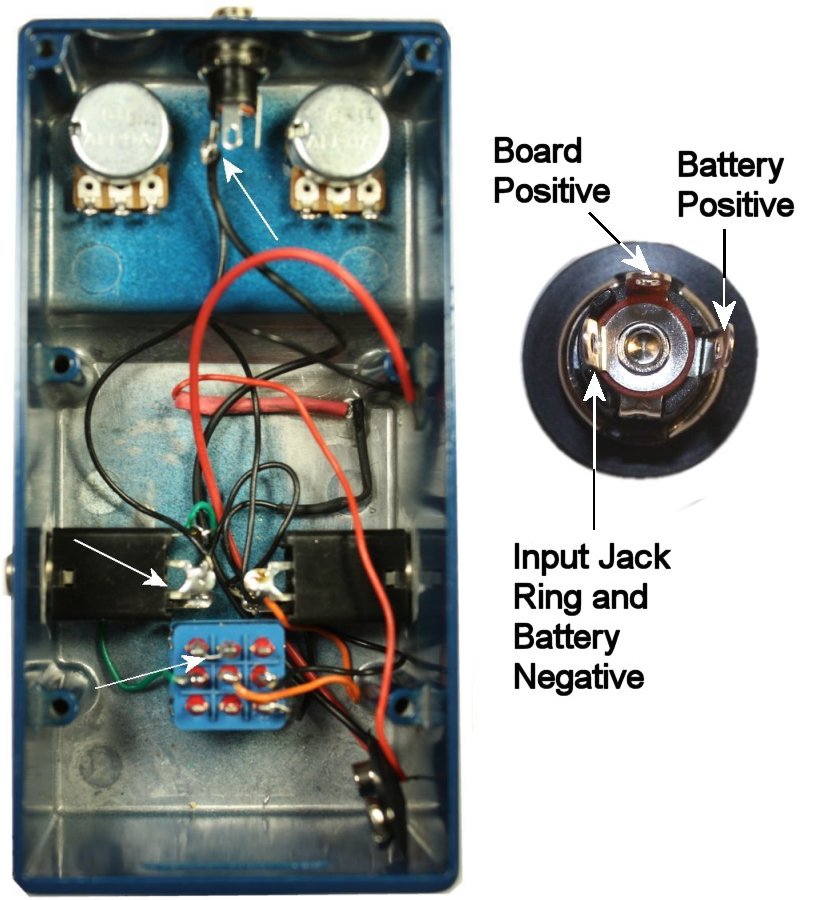
Solder a 5" length of hookup wire to the ring contact of the input jack. Connect the other end of this lead with the negative battery snap lead at the center pin of the power jack, and solder. Solder the positive battery snap lead to the right-side contact of the power jack.
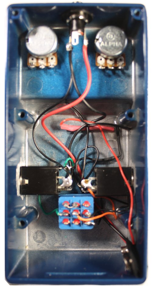
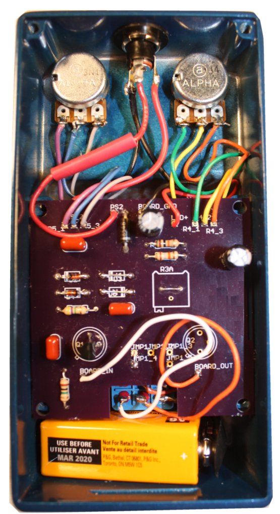
Prepare the board by soldering 3 1/2" lengths of hookup wire to the following points:
- The connections for the two potentiometers
- Battery power in (labeled PS2 or Batt + on the board). Add a 1" length of heat shrink so that you don't forget it later.
- The Board In and Board Out connections
I soldered the positive LED lead and the Board Ground in place, then pots and battery power, then Board In and Board Out.
The wiring is done and we are ready to test the pedal.
- Screw the PC board down
- Tighten all the hardware
- Secure the lid
- Stuff a small piece of foam padding over the battery
- Install the battery cover
- Install knobs
- Attach rubber feet to the bottom
First step is to re-examine the PC board and compare with the fully stuffed board in the instructions.
- Is every component installed?
- Are the correct resistor values installed and in the correct places?
- Are the polarities of the electrolytic capacitors correct?
- Are the diodes and transistor(s) oriented correctly?
If you are sure that everything is correct on top, remove the hardware from the pots, jacks and stomp switch. Very gently, remove the whole assembly from the enclosure and examine the bottom of the board. You should be working under a strong light, and a magnifying glass can be helpful. Make sure that all of the solder pads are filled and solid; poor soldering is a leading cause of failure to work. If you find a problem, fix it and try the pedal again before re-assembling.
If the soldering looks good, review the wiring of the off-board parts--especially the connections to the jacks and the stomp switch. Again, fix any mistakes and try the pedal.
If you breadboarded the circuit before you built, you already have some idea of how to read a schematic and use a multimeter. But the soldered build includes bypass switching, a power jack and an in-use LED. For troubleshooting purposes, here are some notes on how those features actually work and how to use your meter to smoke out problems.
3PDT True-Bypass Switching With In-Use LED - How It Works
Here's a bottom view of a typical 3PDT (Three-pole, Double-throw) footswitch. It has nine contacts, and they work as shown in the schem. Push/release once and the moving contacts (2, 5 and 8) connect to #3, #6 and #9. Push/release again and they go back. We call this a "latching" or "alternate-action" switch, because the contacts remain in their new position when you release the switch.
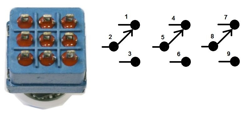
In the schem, the effect is bypassed. The guitar input goes from the moving contact, pin 2, through stationary contacts pin 1 and pin 4 (which are connected with a jumper) to moving contact pin 5 and then to the output jack When the switch is stomped, the input jack sees the effect input through pin 3, and the output jack sees the level control through pin 6. Two contacts of the third pole switch the LED on and off.
Yes, there are other ways to wire a stomp switch, with and without an in-use LED. They will all work, though some may be more suitable than others in a particular design situation. If you want more information, check the Beginner FAQ at diystompboxes.com, or other on-line sources.
Power - Internal and External
While we were on the breadboard, we switched power by disconnecting the battery. That won't work in a pedal, so we have to make some arrangements. And there are several issues:
-
We want a DC power jack, and we want the battery to be cut off when an external power supply is plugged in.
-
We want the circuit to be protected from reverse connection of power.
-
We want battery power to be cut off when the guitar plug is removed from the input jack.
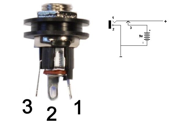
Most modern pedals accomplish all of this in the same way. External power comes in through a jack like the one in Fig. 4. This style is designed to be mounted on the panel of an enclosure, while others mount on a circuit board. Its schematic is shown in on the right. Contact #1 connects to the shell of the power plug, which will be positive in the typical negative-ground pedal design. Contact #3 forms a normally-closed switch with contact #1; it shorts to #1 until a power plug is inserted. Contact #2 is the center pin, which will be ground in this configuration.
Diode D1 takes care of reverse polarity protection; it will block current flow if the battery or power supply is connected incorrectly.
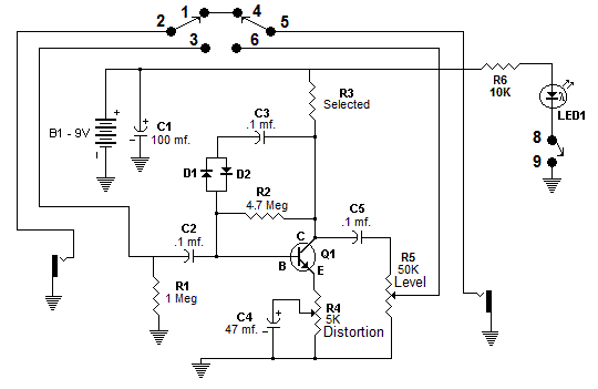
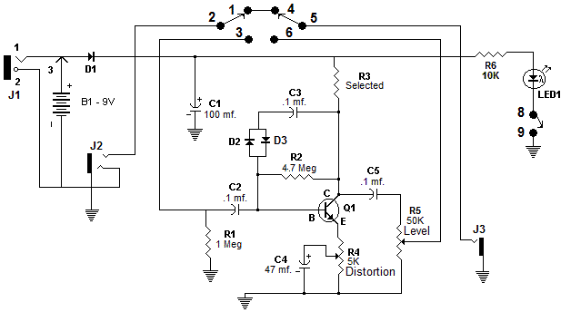
On the left is the whole schematic of the basic build of the pedal, including all of the support circuitry. On the right is an "X-Ray" view of the PC board showing the interconnections.
| I hope that you enjoyed building the Ursa Minor, and that the ideas inspire you to try other builds on the Bare Box #1 platform. Comments and suggestions are welcome at smallbearelec@ix.netcom.com. |