Breadboarding The Ursa Minor
This is a more complex schem than the LED demo in the intro, but it's still little more than a dozen parts including the battery...not too tough. I have purposely not included jacks, stomp switch or power switching in order to keep it simple; we'll add those when we do a soldered build. The only things to note right now are:
-
Where wires cross in a schematic but Don't connect, you'll see this:

-
Where wires cross or join in a schematic and Do connect, you'll see this:

-
The Ground symbol
 is not a connection to the Earth; it's the
reference point from which all voltages in the circuit are measured. All
points in the circuit that have or share the Ground symbol are connected. If this is
not clear yet, you'll get the idea as I walk you through the build.
is not a connection to the Earth; it's the
reference point from which all voltages in the circuit are measured. All
points in the circuit that have or share the Ground symbol are connected. If this is
not clear yet, you'll get the idea as I walk you through the build.
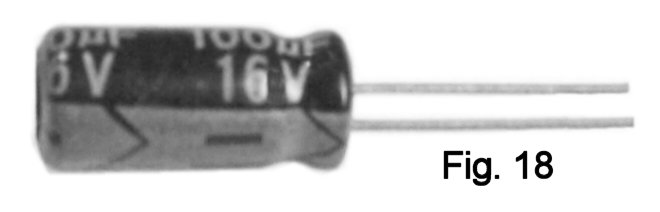
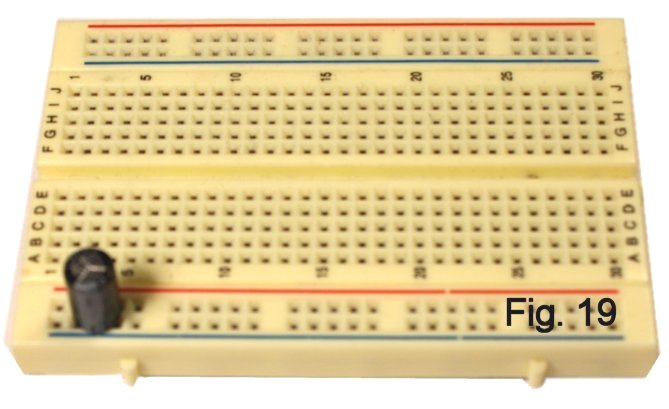
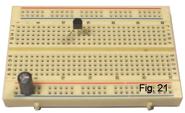
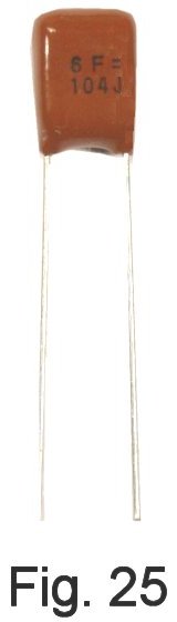
So let's go! Trim the leads of a 100 mf. ("microfarad") electrolytic capacitor, following the convention of leaving 1/4" to 5/16" of lead length for insertion in the board. Electrolytic caps are most often polarized; on radial-case types like this one, a black band marks the negative side (Fig. 18.) Install the capacitor directly across the power rails in the third vertical set of contacts (Fig. 19.) While the part could go anywhere on the power rails, I am being very prescriptive so that your layout will be identical to mine and so easier to debug if necessary. Follow my footsteps (bear tracks?) and layout this time around; once you have the idea, you're free to do whatever works.
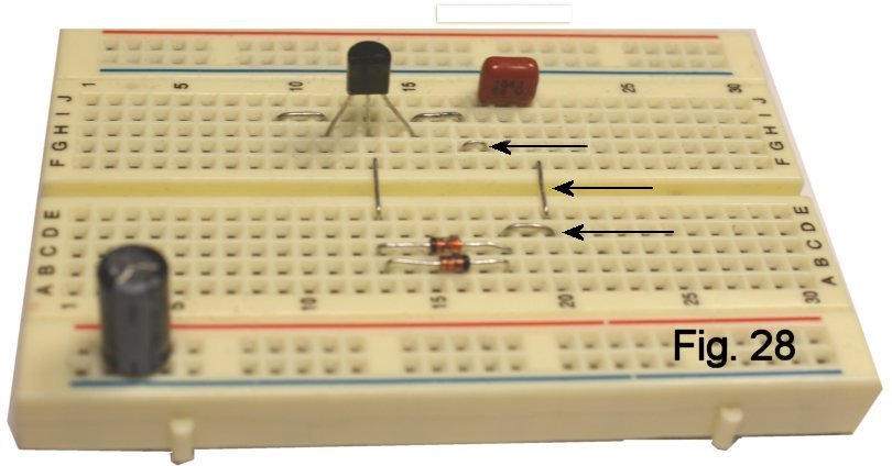
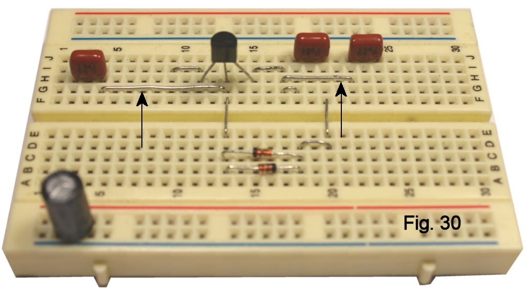
Insert the capacitor between column 18 and column 20 in the first row. The diodes go "back-to-back" (black bands opposite each other) in the second and third rows between columns 13 and 18 (Fig. 28). Three jumpers are needed (2 holes, 4 holes, 3 holes), and I have pointed to them. You have made your first connections! Fig. 29 shows the points in the schematic that you wired. Got the idea? My choices for these component locations were arbitrary, but they turned out to be perfectly workable as I added more parts and connections. When you get to "rolling your own," if your first choice of a location doesn't pan out, back up and try somewhere else!
Capacitor C4 is a 47 mf. electrolytic. Form the leads to span four holes and install in column 7, paying attention to the polarity marking. Add the jumper to ground on the negative side.
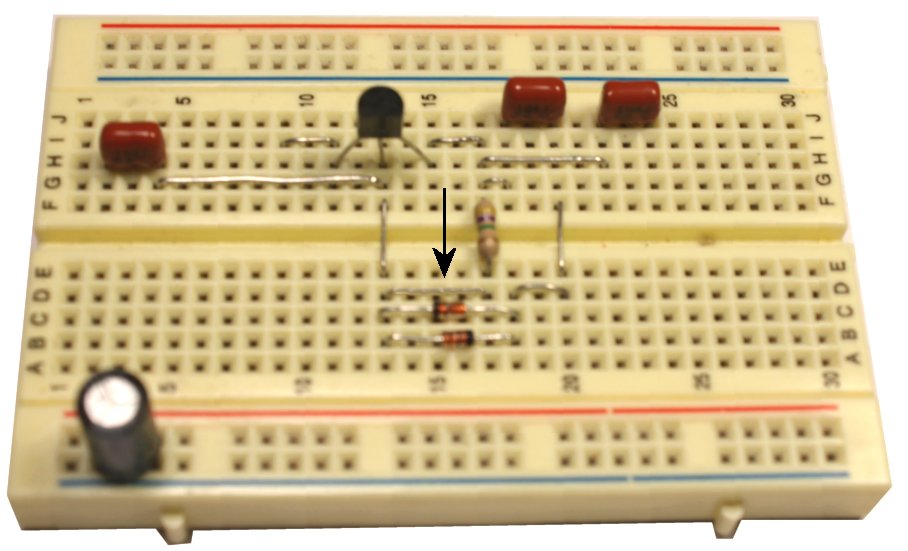
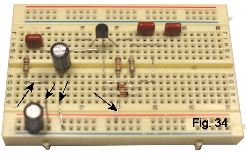
Resistor R3 connects between the Collector of Q1 and the positive power rail. It's labeled "selected", and you'll find right value bagged with the transistor if you bought the kit. If you are rolling-your-own, it's nominally 18K (Brown, Gray, Orange, Gold) for a typical 2N5089 transistor. I will talk later about how to trim the value and why that's desirable. Again, form leads to span four holes and install to the left of R2. Add the jumper to the positive supply rail. We are getting close (Fig. 34 and Fig.35).
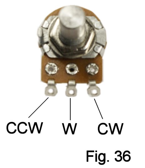
Prepare the distortion and level potentiometers for connecting to the breadboard by soldering leads to them. A few inches of insulated breadboarding wire to each terminal is fine. By convention, we refer to the terminals of the pots as ccw (counter-clockwise), W (wiper, for the moving contact) and cw (clockwise) (Figure 36.) The connections are:
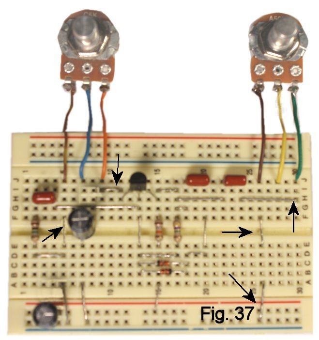
CCW of both pots to the ground bus
CW of the distortion pot (labeled C5K) to the Emitter of Q1 (needs a 3-hole jumper)
Wiper of the distortion pot to the + of C4
CW of the level pot (labeled A50K) to one side of C5 (needs a jumper to span seven holes)
The wiper of the level pot will connect to the output jack. See Fig. 37 and Fig. 38 for what things should look like now.
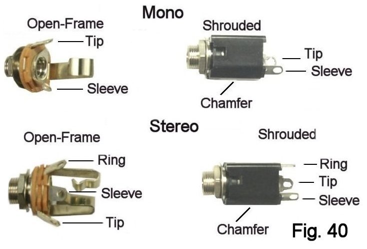
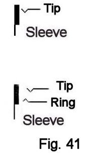
In a typical pedal build, we would use a stereo jack for the input and connect the ring contact to switch battery power. To keep things simple here, we use only the tip and sleeve. Connect a short length of insulated wire to tip and sleeve of each jack. Add bare wire terminations to the ends that go to the breadboard just as you did for the battery snap. Yes, shielded cable would reduce noise here. However, it's harder to work with and not necessary for test purposes.
The sleeve leads are plugged to the ground bus. Input tip goes to the junction of R1 and C2, output tip to the wiper of R5. Things should look like Figure 42.
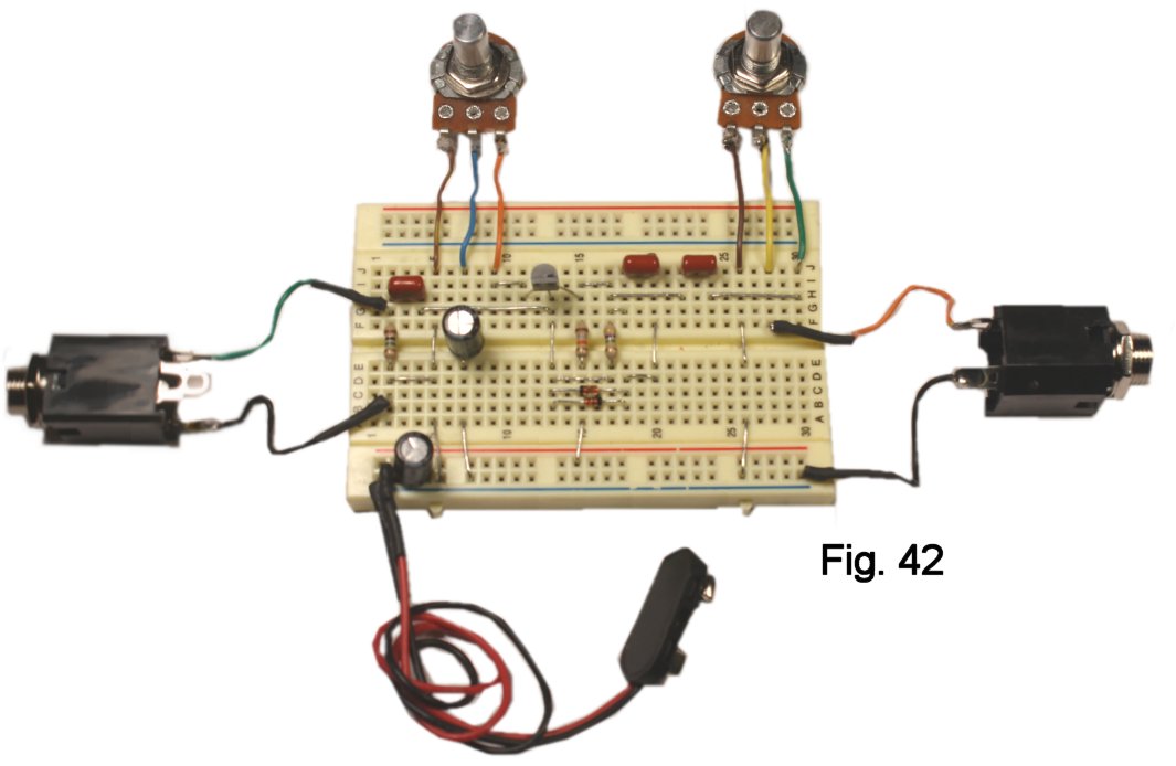
ARE YOU READY?? Connect your amp and connect a battery. Turn up the level control and turn up the fuzz pot till you hear distortion. Try playing with it a bit.
Doesn't work? Go back through the pics and figure out what isn't connected right. Also be sure that:
All component values are correct
Polarities of the electrolytic caps are observed
Transistor pinout is correct
I have built exactly as shown, and the instructions have been vetted by my assistant as well, so we are sure that your build will work if everything matches the instructions.
The Distortion Control
"Taper" in potentiometers is the relationship between percent rotation and percent change in resistance. If you didn't buy the kit and are using a linear taper pot for R4, you'll probably notice that the control of distortion is tight at the clockwise end. The reverse audio taper pot in the kit corrects this problem.
- Clean Boost
Remove C3 so that the diode loop is disconnected. You'll notice that the volume goes up A Lot, and there is no distortion (unless the level pot is so high that you are overdriving your amp!) Yes, it's possible to add a switch to make/break the loop when you do a soldered build.
- Biasing The Transistor
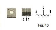
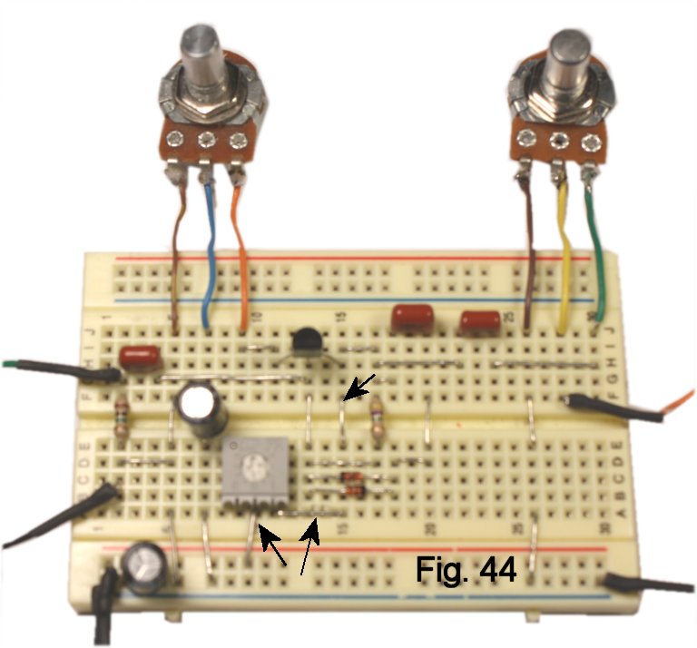
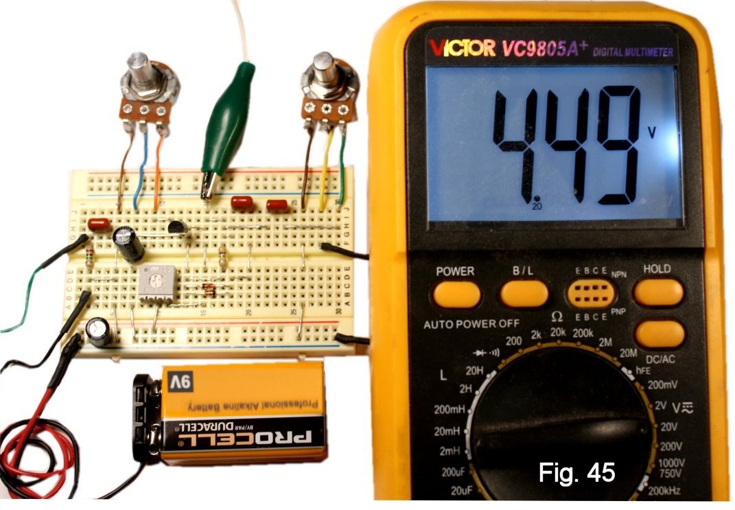
Other clones of the Electra that I have seen do not suggest changing the DC bias. If you substitute a 25K or 50K trimpot for R3, you can adjust the operating point so that the transistor is more "on" or more "off". Figure 43 shows top and bottom views of one of my SKU 1015 cermet types along with its schematic symbol. When installing it on the breadboard, install a jumper in place of R3 and add two jumpers to connect the trimpot (Fig. 44). Start with the adjusting screw at about the halfway point before applying power. Try playing some licks with the bias at various settings. I like the result with the voltage at the Collector of Q1 around half the supply voltage (Figure 45).
- Different Transistor Types/Darlingtons
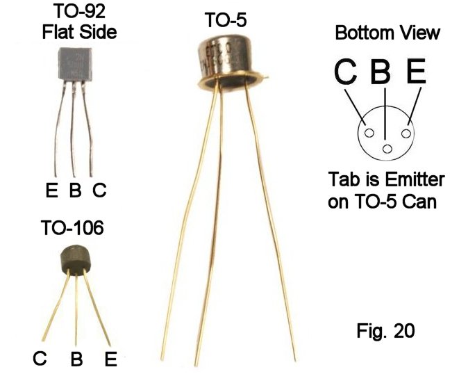
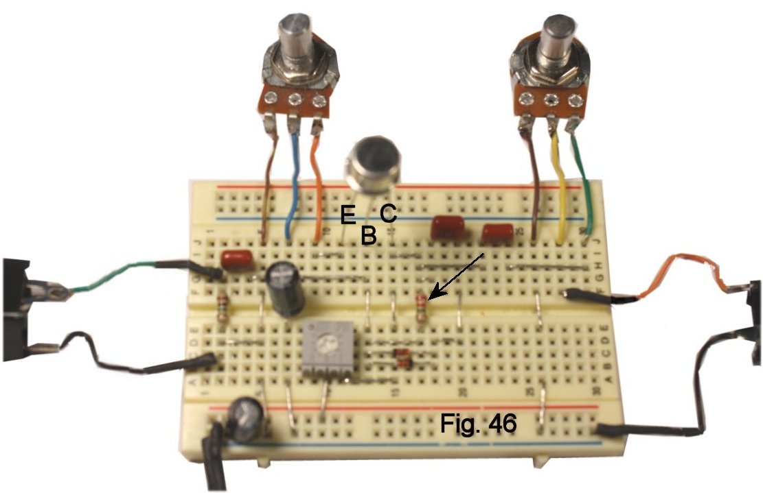
Some versions of the Electra used a 2N3904, which can have a gain of less than 100--not enough to ensure that the diodes will clip strongly. For silicon, I suggest a 2N5088 or 2N5089. A Darlington transistor like the MPSA13 will also work fine. I did not hear any difference in tone between these devices when biased similarly. On the other hand, to my ears, a high-gain germanium device gives a softer edge. It plugs in the same way as the 2N5089; just pay attention to the pinout, referring to figure 20 if you need to. I lowered R2 to 2.2 Meg in order to get the range of bias control where I wanted it, YMMV (Fig. 46).
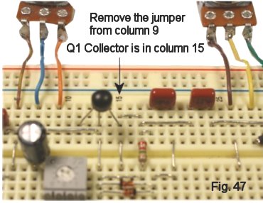
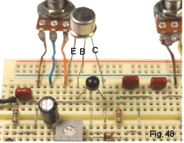
An interesting result to my ears came from a Darlington pair--two cascaded transistors--made from a low-gain NPN silicon "dot" feeding the germanium device. The jumpering needs to change a bit to accommodate the two devices; refer to the detail pics figure 47 and figure 48, and pay attention to the pinouts and the schematic (Fig. 49).
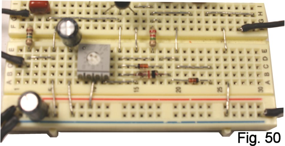
- Diode Types/Asymmetrical Clipping
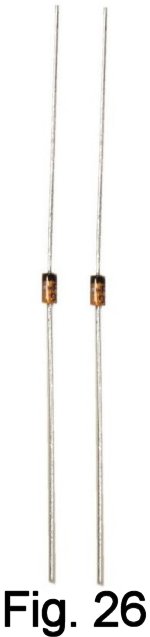
Each diode in the loop clips one half-cycle of the signal, so a loop using two diodes of the same type will clip both halves equally. Germanium has a lower threshhold voltage for conduction (Vfwd) compared to silicon, so inserting a germanium diode will result in one half-cycle being clipped more than the other (Fig. 50, 51). The difference in clipping is noticeable, and hard to describe...to my ears maybe a little less "squished" than all-silicon. Numerous combinations of diodes (and LEDs) will work, and the differences in Vfwd and internal capacitance will give different timbres.
- Input And Output Capacitors
Reducing the value of the input capacitor to .01 mf. gave me an "in the pocket" tone that some players would probably like in particular lead passages. Reducing the value of the output cap cuts out some low end, which you might like, but it also reduces volume.
Where To Go From Here
In the article that follows this one, I will show how to wire the circuit on perfboard and create a finished pedal in the Bare Box #1. I hope you enjoyed learning to use the breadboard, and that you will use your new skills to hack into other designs and try out your own ideas.