Breadboard A Germanium Darlington Fuzz Face
By Steve Daniels, Small Bear Electronics LLC
© 2014 By Small Bear Electronics LLC
|
In a previous article, I showed how to use inexpensive, low-gain NPN
germanium transistors in Darlington pairs to duplicate the performance of expensive, higher-gain bucket devices for the Rangemaster. Having
succeeded with the RM, I have applied the same idea to the Fuzz Face. Here
are ways to create beautiful-sounding classic Fuzz Faces and Tone Benders
using cheap parts that were long-ignored.
How did we end up here? Simple economics: Back in the '60s, NPN germanium devices with decent gains and low leakage were hard-to-make and way more expensive than PNP, so pedal-makers took the path of least resistance (no pun intended). Today, everyone still wants devices in the 70 - 140 range, because their uses are well-characterized. But if you are willing to experiment, there are some fairly large stocks of both NPN and PNP low-gain devices that can be re-purposed with happy results. For the moment, there are many choices and prices are reasonable. |
||
| Pre-requisites: This article draws on my notes about Darlington pairs in my Rangemaster How-To. Newbies to these circuits, please start there and maybe even breadboard a Darlington RM to get your feet wet. If you have never used a solderless breadboard, please refer to the intro article on breadboarding before you continue. That How-To covers a lot of basic information and techniques; I presume that you have been through it, have done the demos, understand how the tool works and have started learning to use your multimeter. Especially important is knowing how to characterize germanium devices for gain and leakage by the Bare Bones method shown in this FAQ. | ||
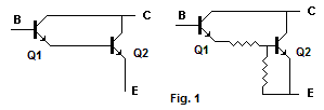
| A Darlington Pair For The Fuzz Face First Stage | ||
| The "ideal" single transistor for this has a gain of 70 to 85, right? To simulate it with a Darlington pair, we might--If we were really lucky--find a couple of parts with gains under 10 and very low leakage. In my experience, that combination will drop into the FF circuit with no other changes. But since Mother Nature doesn't usually smile on us so directly, it's more likely that we will need to turn the second device "off" enough to bring the composite gain down to where we need it to be. Figure 1 shows the idea: the two resistors form a voltage divider that puts the Base of Q2 closer to ground or closer to the current source represented by the Emitter of Q1. |
|
|
|
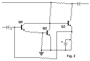
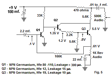
Figure 2 shows the gain block represented by the Darlington pair dropped
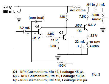
into the familiar Fuzz Face circuit. From having simulated an 80-ish gain device for the RM, I already had a rough "recipe" for the gains and leakages of the Darlington transistors and approximate values for bias resistors for that section. So I started with the pair shown below, added a typical "good" 2nd stage FF device and the four standard Fuzz Face bias resistors. Figure 3 shows what I breadboarded, with voltage readings and notes on what the devices are. |
|
|
|
To set the values of the bias resistors in the Darlington stage, I started with two 10K trimpots set to about their mid-points. While measuring the voltage at the Collector of Q3, I adjusted the pots back and forth to get a reading between 4.5 and 5.75 volts on the Q3 Collector. Then I measured resistance and subbed the nearest 5% values. |
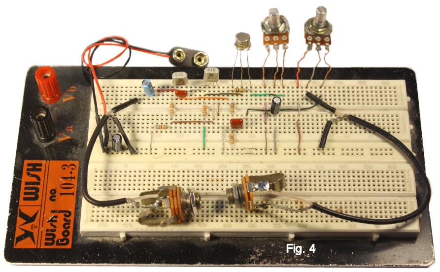
At this point, I set up for my first listen. I found that I needed the capacitor from Collector to Base of Q1 (.0022 to .0047 mf.) to keep the circuit stable at the full fuzz setting, and I tweaked the Q3 Collector load a bit. With those minor changes, it's the stock build. It sounds like a solid FF, and it only needs one relatively-scarce device. I used a fairly "hot" Q3 here, but anything that you would normally use for Q2 in the FF (100 to 140) will work. More applications for parts from your low-gain silicon bin: To reduce the cost still further and see what would happen, I subbed for Q1 an NPN silicon "dot" with a gain of about 20. This threw the bias out-of-whack on Q3 Collector, so I did the obvious: subbed a 10K pot for the Collector load and dialed in. I'll be danged if the result doesn't sound like an Easy Face! I also tried a 2N3440 with good results, so other very low-gain silicon should also work well. Here is the all-germanium breadboard setup:
|
|
|
|
||
|
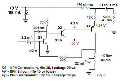
Making Q2 The Darlington Stage It seemed obvious to try this, because some parts bins may have a suitable medium-gain device for the first FF stage but are missing the higher-gain device for Q2. I just moved the Darlington pair to the second stage and tweaked the bias to raise the gain a bit. The first-stage device is a regular Fuzz Face Q1, and I did not need the stabilizing capacitor. The circuit sounds excellent, and it still needs only one scarce part. Again, an 80 to 90-ish silicon device will work for Q1 if you re-bias using a 10K pot or trimpot in place of the Darlington's Collector load. |
 |
|
|
A "Really Szik" Fuzz Face Setting up a Sziklai Darlington pair is truly a way to turn trash to gold. At least until this approach becomes widely popular and prices of low-gain parts go up, you can do an all-germanium or hybrid Si/Ge, negative-ground Fuzz Face that sounds great for very little money. The schem shows what I actually used and how the biasing looked. I needed the the B-to-C capacitor on Q1 to suppress oscillation, but you can get away without it if you use a lower-gain device. Numerous devices will work well for Q2; my breadboard setup used an unmarked 2N334A SKU 1981M. |
 |
|
| If you don't find suitable raw stock for trying these circuits in your own shop, please check the Low Gain and High-Gain category under Germanium Transistors in my Stock List. I hope the ideas inspire some interesting growly noises, and comments and suggestions are welcome at smallbearelec@ix.netcom.com. | ||