| This article is meant for the beginning stompbox builder who wants to learn how a solderless breadboard works and how to use it for prototyping. As a matter of
necessity, I'll also show some basic functions of using a multimeter for
continuity and voltage tests and introduce interpreting a schematic. From that
point, subsequent articles will cover setting up various effect circuits. |
| |
| Why A Breadboard? |
|
| So you have come up with a pinky-new circuit for the World's
Greatest Distortion/Trem/Delay, etc., etc. that will have guitar players
worldwide salivating to put one in their effects loop. You engineer everything
carefully, build with super high-quality components and fire it up. Of course, either:
|
|
|
| The solderless breadboard provides a way to set up a circuit for testing purposes without committing to a permanent build. It's the electronic equivalent of a kid's
Erector set; components can easily be added or removed, and whole sections can be reconfigured as many times as necessary to get to a finished design. |
|
|
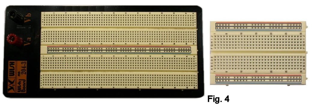
| The models that I use in this article: |
|
|
|
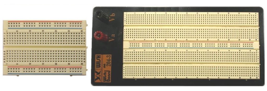
| are typical of many that are available from
mail-order shops. The plastic rails (often called "breadboard strips") are
made in several sizes, and they can usually be snapped together to create
larger arrays. For simple builds, a small strip like the one on the left is
usually fine. On the right is a typical product that has larger strips
attached to a metal base, convenient for bigger
layouts. More complex and expensive versions exist, some of which include built-in power supplies and mounting brackets for controls. My directions will mostly be applicable to anything you buy, whether from my Stock List or anywhere else. |
|
| How It Works - The "Bear Bones" |
|
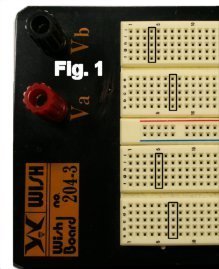
| Within each hole in the plastic rail is a spring-loaded contact that will
positively grip the lead of a component that you insert, but still allow you to
remove it easily. Each column of five holes is connected internally (Fig. 1). It
may help you get oriented by actually satisfying yourself that this is the case.
Insert short lengths of bare #22 or #24 wire into any two holes in a column (Fig.
2). |
|
|
|
| |
|
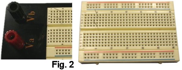
Now set the selector of your multimeter to the Continuity
position (or the lowest resistance scale if your instrument does not have a
Continuity position) and measure between the wires (Fig. 3).
|
| |
|
|
| OK so far? Many breadboards have |
| |
| Busses |
| |
| A bus (in this case) is a row of holes connected horizontally
so that power can easily be distributed to the points in the circuit where it is
needed, and/or to provide a common ground. (I'll get more into that concept and
define it later.) The busses are outlined in figure 4: |
| |
 |
|
Do the test with the multimeter if you need to to be sure that you
know what is--and is not--connected to what. While each bus in these breadboard
is connected all the way across, I have seen models in which the bus is split in
the middle; you have to connect the two halves
together if you want continuity across the full length.
You have probably noticed that the rows on each strip have
letters and the columns are numbered. This "indexing" is sometimes useful for
referring to specific locations, as we'll do later on.
|
|
|
Making Connections
|
|
|
Let's begin by setting up a very simple circuit just to light an
LED. This will demonstrate a couple of necessary points before we tackle an
effect. This breadboard has red (+) and black (-) binding posts for connecting
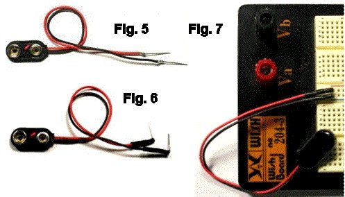
power, but I usually use a 9-volt battery snap to which I have soldered a couple
of plug-in leads. It's very easy to make.
First, cut a couple of pieces of #22 or #20 bare wire about 1/2"
long. Wrap a few turns of the end of each battery lead around one of the pieces
and solder (Fig. 5.) (I will talk about where to find/buy connecting wire for
the breadboard in a minute.) Cover the solder joints with small pieces of 1/16"
heat shrink, and conform the tubing to the joint by rubbing it gently with the
barrel of your soldering iron Then put a right-angle bend in each end, and you
have a connector (Fig. 6.) It plugs conveniently into the busses of the
breadboard (Fig. 7.)
|
|
|
|
| Shown as a schematic, here is what we want to connect: |
|
|
|
| Pretty simple, right? A schematic shows the logical connection
of components, but not necessarily the physical way that they are laid out. So
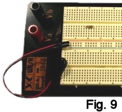
let's lay this out on the breadboard. First, cut off half the leads from a 10K
resistor (Brown, Black, Orange, Gold) and save the wire scraps for use later. Bend the
leads flush to the body, and plug the resistor into any two convenient columns
(Fig. 9); breadboarding is pragmatic and practical and does not have many fixed rules
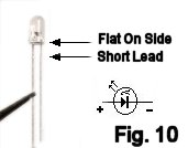
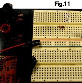
about what goes where. The LED is a diode by definition and so is polarized
(Fig. 10.) Plug it in with its positive lead in the same column as the
right-hand lead of the resistor (Fig. 11.) You have made the connection shown in
Fig. 12. Got the idea? |
|
    |
|
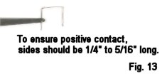
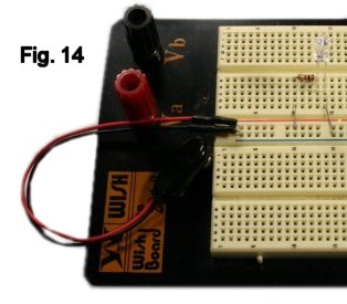
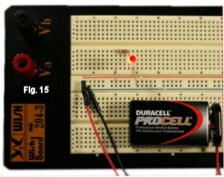
| Now finish the circuit. Create a couple of jumpers
from #22 or #24 bare stock (Fig. 13) and
plug these in to make the connections to the power supply busses (Fig. 14.)
Connect the battery (Fig. 15) and let there be light! |
|
   |
|
A few notes:
-
For purposes of illustration, I squared the corners of the
jumpers and made the hole-to-hole lengths exact, but neither is necessary for
routine work; as I noted earlier, breadboarding is pragmatic and based on speed
and convenience.
-
Jumpers can be made from insulated or bare wire. Use insulated
wire where there is any possibility that leads will short.
-
Wire for making jumpers can be bare or tinned copper, and most
breadboards will accommodate gauges from #20 to #24. You can find suitable
material in Wire and Cable on my Stock List or from other stores, but you can
also take advantage of free sources: Save the scraps of wire that result when you
trim component leads; many of these are perfect for jumpers that need to span
only two or three holes. Also, if you run across a job site where telephone
installation or removal is being done, look out for discarded pieces
of multi-pair cable that contain as many as 50 of these individual conductors
(Fig. 16):
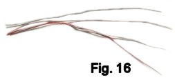
Slice the outer jacket, remove a bunch of these wires, and you
will have all you need for many moons of experiments.
Are you ready to Rock and Roll? OK!!
At this point, you can proceed to the article on
Breadboarding A Silicon Fuzz
Face. I will add other effects to this series down the road. Welcome, and let
the Noise begin!
|