In one of his "Master's thesis" articles, "The Technology of Wah Pedals," R.
G. Keen offered an op-amp implementation of the inductor-type wah-wah circuit.
But, as he sometimes does, Teacher left working out the component values as a
homework problem for his students. I had special reasons that I'll mention later for wanting to tackle
this project, but my first motivation was that the
simplicity of the op-amp circuit made it easier for me to understand the operation of a wah.
For the benefit of others who are where I was before I started this
article, I'll review the "cookbook" analysis that I did to get a working
prototype. Then I'll get into building something practical.
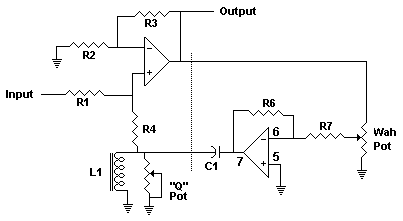
Here's the circuit as it appears at GEO. I have only added desis to the resistors and cap, and a line separating the stages for ease of
discussion:
After reading R. G.'s description of the transistor version (for about the
hundredth time) I had one of those "Oh, that's what he was driving at!" moments
when looking at this implementation: To my bearish mind, the simpler biasing of an
op-amp makes it easier to understand this circuit compared to its discrete transistor
cousin.
How It Works
Ignore for a minute everything to the right of the dotted line, and
imagine that inductor L1 and the "Q" pot are not there; R4 goes straight to
ground. We now have the most basic IC-based preamp circuit that you've seen in a
hundred boost pedals, right? The gain of the stage is equal to R3/R2. R1 and R4
form a voltage divider that sets the input signal level. Simple enough! Now add
back the inductor in the input circuit. By definition, an inductor passes lower
frequencies more easily than higher ones. So a certain amount of bass is shunted
directly to ground, and the op-amp amplifies what is left: the treble. We have a
basic treble boost! This is not just theoretical; once I flesh the circuit out a little bit,
you can do some breadboarding and hear for yourself what it does!
Now visualize the tank capacitor C1 connected from L1-R4 to ground. This
gives us a parallel resonant circuit. Since the inductor is grounding out low
frequencies, and the cap is grounding out high frequencies (caps pass highs and
block lows, right?), the op-amp will boost most strongly at resonance--the
frequency that's just right for neither the inductor nor the capacitor to be
seen as much of a sink.
Now for the second op-amp stage: One way to see it is as a variable
path to ground for the "cold" side of C1. The setting of the Wah pot makes the
output of the op-amp more grounded or less, the cap looks more
part of the tank circuit or less, and the resonant frequency moves: ooooooWWWWAAAAH! The
"magic" happens because the gain of the second op-amp multiplies the
nominal value of the tank
capacitor, and the feedback through the stage to the input sharpens the resonant peak. Do a Google search on the Miller Effect and on active filters if you want to get
further into the theory.
Getting It Working
I came up with a first approximation for the resistor values like this: R.
G. had said in his article that the first stage of the transistor wah circuit had a
theoretical gain in the low 20s. OK, so if I set R3 in this version to an arbitrary 100K, that
would make R2 around 5K. The second stage of the transistor circuit is an
emitter follower, which has unity gain, so I started with R6 and R8 in this
version both at 100K. I added the usual "phantom ground" reference
voltage and set up this much on a breadboard using the primary of an audio
transformer as the inductor. I got a recognizable wah, so I knew I was on the
right track. But the circuit as shown above was not happy with a 100K wah pot; it wanted
more like 10K. I described this to R. G., who immediately saw what I should
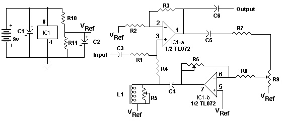
have: A blocking cap is needed between the preamp output and the wah
pot to keep the DC in the output from affecting the bias of IC1-b. Then the wah pot can be whatever value you want. I added a resistor in
series with the pot to help set the range of the sweep, and a coupling capacitor
for the output. Here's the result:
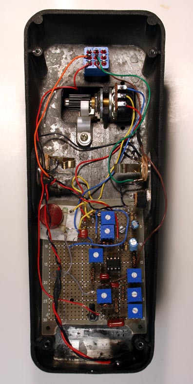
Since I didn't fully know at this point what component affected what aspect
of the wah, I did what
you'd expect: I cobbled a breadboard, with trimpots replacing the
resistors, and mounted it in a shell. This gave me liberty to play, tweak a
little, play again, etc., till I had some idea what components needed to be
adjustable:
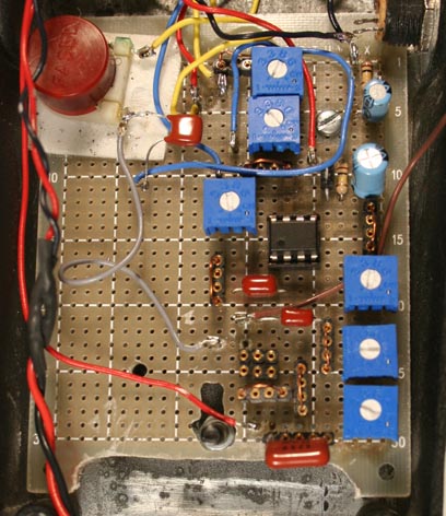
I removed a trimpot before shooting the right-hand detail pic to show my
construction method. As you can see, I installed two three-pin sections of single-in-line
socket material to get, effectively, a socket for a trimpot. The four-pin
section below was for a series limiting resistor in case I needed it. I'm not
going into more detail on this stage of the project, because anyone who needs a
chassis like this for development should be able to work it out from the idea.
What It Sounded Like:
Using the primary of a Mouser 42TM013 for the inductor, and a .01 mf. ECQ-B
film cap for C4, it's a decent-sounding, musically useful wah. The input cap C3
is .022 mf., and C5 and C6 are both .22 mf. The nominal
resistor values were:
|
R1 |
R2 |
R3 |
R4 |
R6 |
R7 |
R8 |
| 100K |
680W |
100K |
1K |
130K |
220K |
1 Meg |
But
I wasn't enthusiastic at this point, so I substituted
an Eleca halo inductor and then a Dunlop Fasel replica to see what purpose-made
parts would do.
With that change, and some tweaking of the bias...This thing HONKS! It QUACKS! It's VERY funky, vocal and throaty! The inductor makes all the
difference in the world to the tone. A couple of sound clips:
Wah#1
Wah#2
There is a lot of rushing white noise at the high-frequency end of the sweep, as
R. G. had let me know there
would be, because of the nature of the circuit. However, I still think that many
people will find it musically useful. Playing
around with it, gee... I get some sounds like a...WILD MOUSE!
The WM Connection
I must have been the most naive Bear in the world to think that nobody would
realize that I was aiming for a wah when I came up with the Wild Mouse. That
effect is interesting, and useful in its own right, but it's time to own up: the
I-See is what I had in mind many years ago and didn't know how to do.
The difference between them technically? Regarding the WM, as R. G. noted in his long-ago review: "By
bench testing, the resonant peak does not move up or down in frequency as you
change the resonance knob setting, but it sounds like it does. (italics
mine)" I remembered this comment, and my guess, which I have discussed with R.
G., is that the op-amp output in the WM is "ringing" the L-C--making it dump
artifacts into the mix-- rather than using it as a filter. The audible result, to
my ears, is that the WM is more distorted and less vocal than the I-See. I hope
you will ultimately try both. Many thanks to R. G. Keen for his help and advice with
these designs!
Let's Build An I-See Wah-Wah!
With some experimenting, I found that I could get the control of the
sweep that I wanted by fixing all of the bias resistors except R6 and R7. So I
included pots for those and the "Q" control, and a selector switch for tank
caps. Here's a completed schematic, and a parts list:
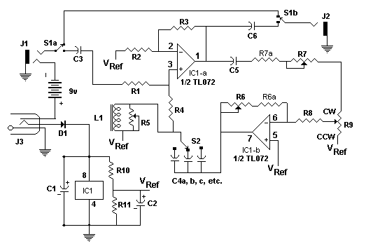

R5a, R6a and R7a are optional series resistors to be added if you need/want to
put a limit on the range of control of R5, R6 or R7, and the board includes
space for them. Here is the layout I came up with:
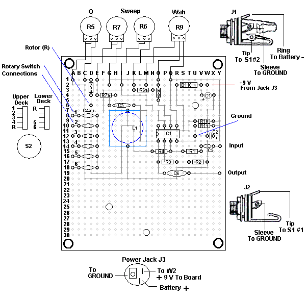
The board is oversized and has a lot of unused space, both because I wanted the
design to be beginner-friendly, and because some builders will want room for
additional inductors, Orange Drop capacitors, or other mods.
I presume that you are using either the Eleca shell that I offer or a comparable
Crybaby-compatible chassis. If not, some-dimensions may differ.
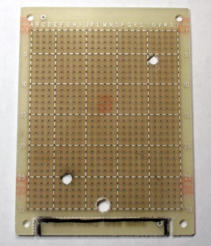
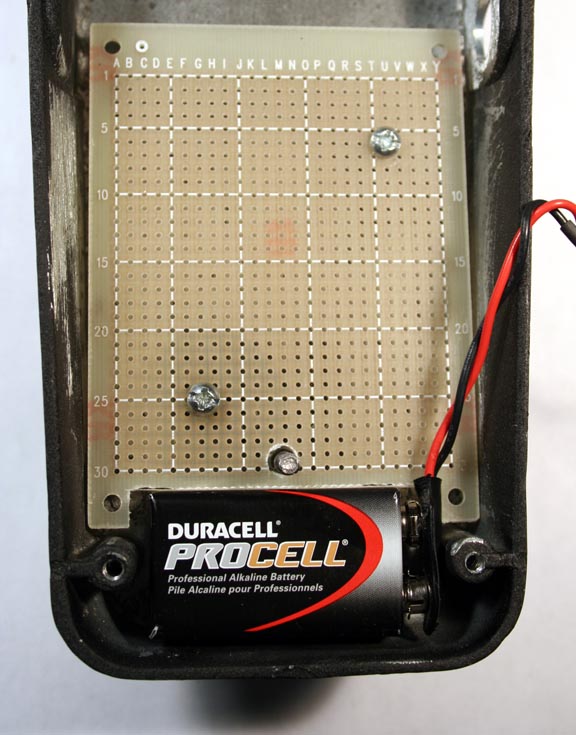
Start to tool the board by boring the mounting holes at U6 and G25. If you
notice that the screws on mine look larger than standard, they are: I stripped
the threads in the standoffs because I installed and removed the board so many
times during design, so I tapped the holes again for 6-32. The standard hole is
for a #4. The screw that holds the rocker assembly is a #6, and this needs to
pass between indexes M29 and M30.
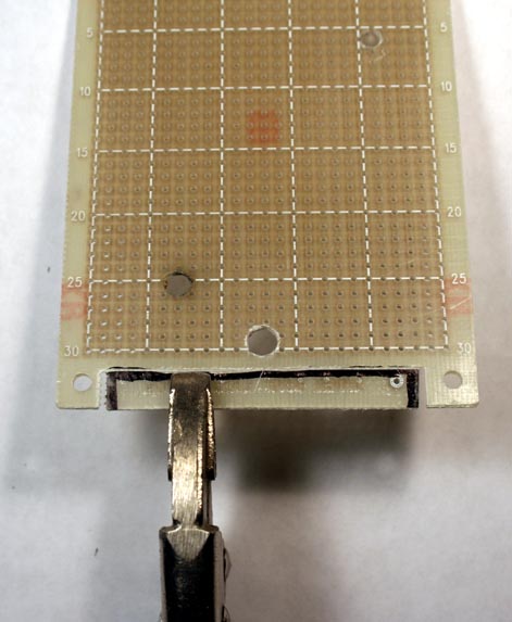
Make the cutout for the battery by marking off the area to be removed and then
scoring a horizontal line across the top with a steel rule and knife. Make the
cuts at the sides with a small file or a cutoff wheel on a Dremel tool.
Fiberglass fragments and dust are noxious,
so wear disposable gloves and a filter mask when you do this job! If you do use
a cutoff wheel, remember your goggles! Snap out the rectangular segment by
"nibbling" at it with pliers. By nibble, I mean bend at the point where you are
grabbing just enough that you feel the fibers break. Then move the tool sideways
for the next bite. When done, clean up with a flat file
or sanding block. Screw the board down and make sure everything fits:
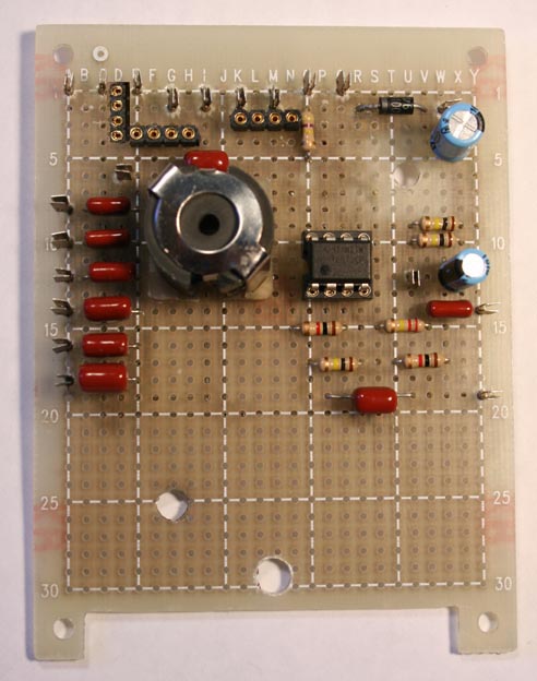
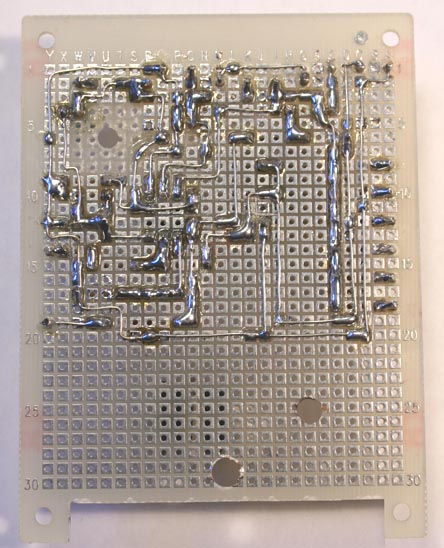
OK so far? Then stuff the board as shown in the layout drawing and the pics.
This is an easy one, not much more complicated than the Tweak-O, really, so
please review that article if you need tips on wiring a pad-per-hole board.
A few suggestions and notes:
- I included four-pin sections of single-in-line socket material so that I
could easily add R5a-R7a.
- I suggest a fixed 470K resistor for R8 if you are using an Eleca Halo
inductor, 620K for a Fasel Red.
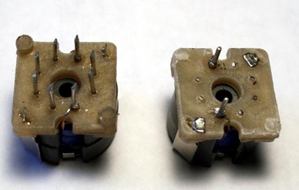
- If you use the Halo, cut off all of
the unused pins as close as possible to the base. Also, so that the assembly
will sit as low as possible in the chassis, bend over the tabs of the retaining
clip and grind or file down the stumps on the plastic base.
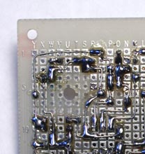
- To make sure that
the upper mounting stud wouldn't accidentally short anything, I used my soldering
iron to remove the pads surrounding it:
I have recommended this in other articles, but I will repeat it here in case
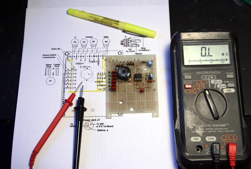
this is the first of my designs that you are looking at: The best way I have
found to ensure that a build works on power-up is to do a continuity check on
every joint and trace, and then mark off the tested run with a highlighter:
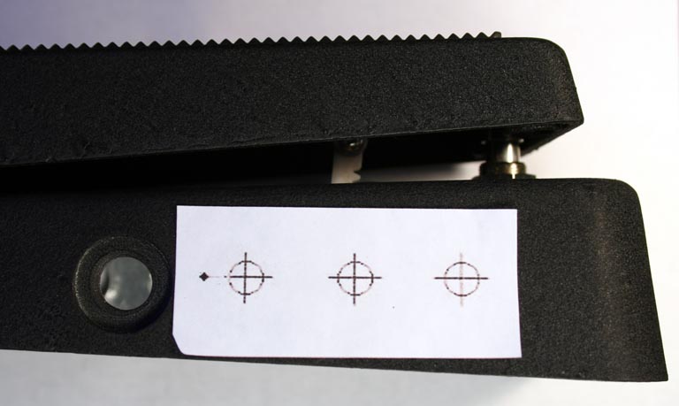
Before mounting the board for wiring, the chassis needs to be tooled to accept
the potentiometers and the rotary switch. Getting four controls onto one side
comfortably would dictate 9mm pots, which are expensive. I wanted to be able to
use standard 16mm, so I compromised by putting R6, R7 and the switch on one side
and R5 opposite. To get the template for three 16mm controls in a horizontal
row, I printed a copy of the template that I created for the
five-knob pedal
shell and cut out a section. Then I attached this in place with double-sided
scotch tape and scribed the centers for drilling.
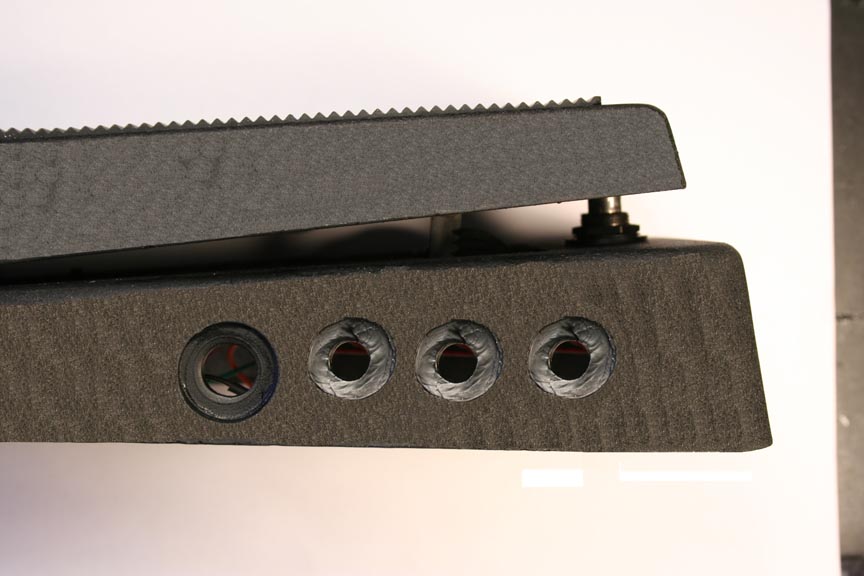
The bushings of the controls are just long enough to penetrate that heavy
casting. However, if you have a Dremel handpiece and a cutting tool, I suggest
creating countersinks for the nuts and washers. I restored the black finish with
regular spray enamel:
Now mount all of the controls. Again, a couple of suggestions:
The stomp switch comes with two nuts. The lower one sets the height of the
plunger off the chassis, and you can adjust this to taste.
To mount the Wah pot (assuming that you are using a Black Bear, or one of the
other ProPot variants), first turn the tension clutch 90 degrees to the left.
Install the pot and tighten its mounting nut. Rotate the pinion gear as far
forward as it will go. Now, with the pedal in the down position, engage the rack
and pinion gears. Turn the tension clutch back toward 12 o'clock, bend it
slightly and ease it into position against the rack. Mount the rest of the
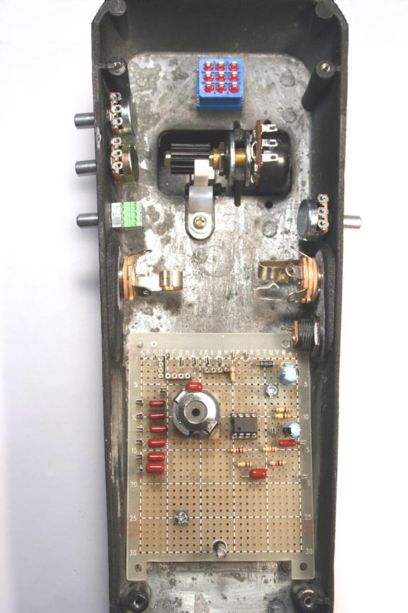
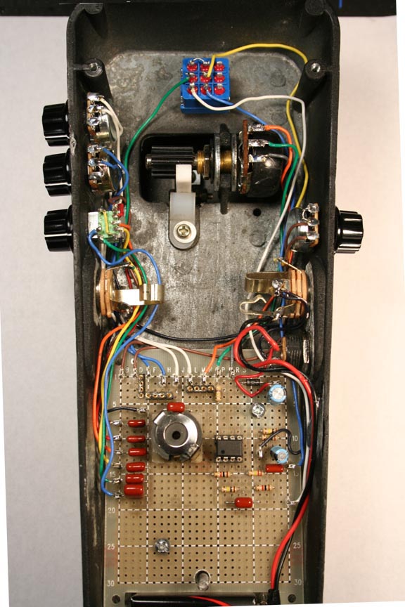
parts, and we are ready to wire. These pics show the before and after:
CRANK IT UP! - Setup and Testing
Start with R5 at maximum resistance. Use an ohmmeter to set these approximate
resistance values for R6 and R7, and then install jumpers in place of R5a, R6a
and R7a. Connect a battery and your amp, and see if you have a Wah.
|
|
R6 |
R7 |
| Halo |
82K |
140K |
| Fasel |
80K |
80K |
With the Halo inductor, I wound up adding a 10K resistor as R6a and 51K as
R7a to get ranges of control that I was happy with. YMMV, especially if you use
a different inductor.
Troubleshooting
If you get no sound at all, first make sure that the chip is getting powered
(about 8.75 volts at pin 8). Also make sure that Vref is about half the supply
voltage, and that it is getting to the points where it is supposed to be. If the
power is OK, use your amp as an audio probe to see if maybe you have made
mistake in the wiring to the external components. If you are still stuck, go
back to the technique of testing each joint and trace and marking off
connections--it works! I built the model you see here from the posted drawings,
and I am confident that they are correct. However, if you do come across an
error, please let me know so that I can help other builders.
I hope that you enjoyed building the I-See Wah! Please direct comments and questions to smallbearelec@ix.netcom.com.