(aka: Not Your Mother's Fuzz Face)
By Steve Daniels, Small Bear Electronics LLC
© 2005 By Small Bear Electronics LLC
Everyone who has ever built a Fuzz Face (which has to be almost every DIYer out there) has been amazed by just how much great sound can be had from such a simple circuit. But the original design had built-in limitations: Its output wasn't always loud enough, there was no tone control or in-use LED, and control of the distortion wasn't great. I built my first Bear Face five years ago to offer solutions to these issues. While I was happy with the result, I did not then have access to some of the OEM parts that I now import. Also, I have since learned and worked out a lot of useful construction ideas. This re-designed Bear Face is my take on what what you might like the FF to work and sound like: louder, with more nuances of tone and distortion and more sustain. It isn't an "over-the-top" effect; if you are looking for that, build a Tone Bender Pro MkII. But it is a wonderfully tweakable, fun-to-fiddle-with fuzz for indulging your Hendrix/Clapton/Page fantasies. It incorporates a TL071 BiFET IC as a post-FF overdrive, a Big Muff Pi tone stack, and a driver for an in-use indicator LED. Add to this true-bypass switching and an external power connector, and you have a most versatile, compact and inexpensive-to-build example of a classic stompbox.
The theory of operation of the basic Fuzz Face circuit has been well-covered by R. G. Keen, so I will not repeat that here. However, I will mention a few things about my additions. Here's the schematic:
Beginners may find the power switching a little confusing, so here is how it works: The positive side of the battery and wall wart (ground in this case because I used PNP transistors) are fed to the "ring" contact of input jack J1, a three-contact stereo type. When the plug of a patch cord is inserted, the sleeve of the plug will short the ring of the jack to the circuit common ground, completing the power circuit. The negative power feed goes through diode D1 (prevents damage from accidental power reversal) to index D9 on the board. When a wall wart is inserted, the battery negative is disconnected.
Clean-up pot R2 is optional. I like having it, because I can kick in the BF with my guitar volume dimed and know that I don't need to do any more adjustment. Distortion pot R7 was always linear taper in the original, but this puts almost all of the effect of the control into the last 10% of its rotation. Reverse audio taper is preferable here, and you can find the right pot on my stock list. IC1 is set up as the simplest possible inverting amplifier, which gets overdriven as R8 increases the input from the FF stage. I did not add any tube-screamerish mods to the gain loop, but that is certainly possible. The output from the tone stack feeds the usual level control.
For true bypass with in-use LED, I re-worked the "RAT bypass" circuit using a cheap, commonly available PNP darlington transistor. Its base is held to ground when the effect is bypassed as shown in the schem. R16 biases the device on when S1b switches the wiper of R14 to J2. R15 limits the LED current and D2 presents it with a consistent voltage as the battery ages. In my proto, R16 is 5 x 22 meg in series, though 100 meg 1/4 watt resistors can sometimes be found as surplus. The same space on the board will easily fit R. G. Keen's Millenium bypass, or a series resistor tied to a 3PDT switch.
Building It:
I don't offer a kit per se, because there are just too many possible variations that I know people will want to try. But you can find everything needed to build to your taste in my stock list. For those who want a duplicate, I will document exactly how I did what you see here and provide an itemized parts list.
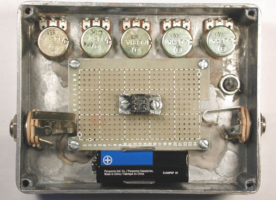
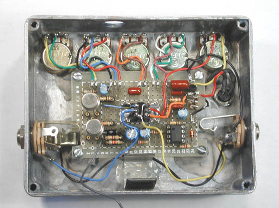
In doing this re-design, I worked out a standard layout for the "shell" or "wrapper" (R. G. Keen's term) for a pedal with up to five knobs set on the long edge of a "BB-size" enclosure. The construction is documented here. Refer to that article, and tool and decorate the enclosure before you construct the board for the Bear Face. The board layout below uses the "bypass-on-board" technique described in the article on the shell, but you may also use a standard stomp switch. Here is the interior of the case with all of the fittings installed except for the DC power jack:
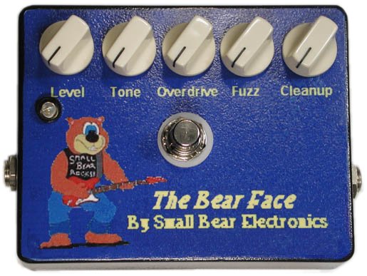
The drawing of the board presumes that you are doing the bypass and LED switching using bypass-on-board and the "RAT-bypass"and LED driver in the schem. If you use an Alpha or similar DPDT switch, follow the contact orientation and numbering shown for a stomp switch.You should be at this point before you proceed. See the schematic and layout drawing for the values of the pots. A note on decorating: I got the "almost silk-screened" appearance that you see above by using Avery #3279 Ink Jet Iron-on Transfer stock. Excellent material, and very easy to use! I did find it a little temperature-sensitive, so, as with Press N' Peel, I suggest doing a test application to learn the best setting for your iron.
Stuffing The Board
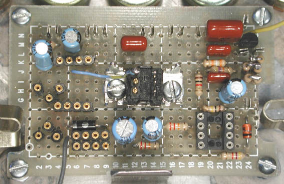
Here is a pic of the assembled board prior to wiring, and some notes about how I got to this point. I will not give you a step-by-step, since the wiring techniques are the same as those for the Tweak-O. Please see that article (and maybe build one?) if you have no experience working with pad-per-hole perfboard.
I used push-in terminals as tie-points for almost all of the off-board leads, except at two indices (C5 and N24) where the layout was too tight to permit. I ran leads directly from those points before mounting the board on the studs.
Check out the wire from index J6 to contact #1 of the switch. It is soldered to one pin of a three-pin section of single-in-line socket material. This construction provides for both secure connecting and easy removal when replacement is required. Make the joint as close to the bottom of the pin as possible, and cut off the excess.
To ensure that the transistors would not be damaged by soldering heat, I used individual socket pins to mount them. The four-pin segments will hold the bias resistors for the Fuzz Face section to make it easy to set up later. Here is the component and wiring layout:
Follow all the usual procedures for building from a layout drawing: Make a clean copy of the drawing, and mark off each connection with a highlighter as you work. Use your ohmmeter as you go to make sure that joints and traces are solid. I built from the above drawing and only forgot one connection; I fixed that, and my proto worked right off the rip.
Testing, Tweaking, Troubleshooting
Bring the wiring to the point shown here: all done except for battery snap and power jack. Insert a pair of Fuzz Face devices with the bias resistor values that you would use with them in a straight Fuzz Face. DON'T CLIP THE TRANSISTOR LEADS YET.
Temporarily connect a battery or power supply (MUST BE WIRED CENTER POSITIVE!) and your amplifier and guitar. Try the controls and see if you have a working pedal. If not, time to start looking for mistakes! If you have fuzz, finish the wiring and you can do some tweaking.
To provide a stable baseline for testing and documentation, I powered the pedal with an external supply set to precisely 9.0 volts (What, you don't have a Small Wart yet??). Note that the polarity protection diode D1 drops the actual supply voltage by .6 volts. If you want the circuit to see more than 8.4 volts, you can use a 1N270 or other germanium power diode for D1, or you can run your supply input higher.
With Q1 and Q2 of 90 and 150 respectively, I started out with the standard bias resistances: collector load Q1 - 33K; b-e feedback - 100K; top of output divider - 470 ohms; collector load Q2 - 8.2K. My measured voltages were:
|
Collector |
Base |
Emitter |
|
| Q1 |
-.71 |
-.14 |
0 |
| Q2 |
-3.6 |
-.71 |
-.592 |
The usual recommendation for correct bias is to have the collector of Q2 at half of the supply voltage, or about 4.2 volts. I pulled out R4 and R5 and stuck in a trimpot to get the total resistance needed to hit that--turned out to be about 7.5K. Now I connected up guitar and amp and concentrated on setting the values for the output voltage divider. I like a hotter-than-standard output, so I settled on 5.6K for R5 and 1.8K for R4. My new measurements were:
|
Collector |
Base |
Emitter |
|
| Q1 |
-.721 |
-.141 |
0 |
| Q2 |
-4.24 |
-.721 |
-.604 |
Obviously, YMMV, but I am sure that you will like the results! The controls interact with each other, and you can get a wide variety of subtle (or gross!) colorations with some experimenting.
I hope you enjoy your growly new pedal, and I welcome feedback at smallbearelec@ix.netcom.com.