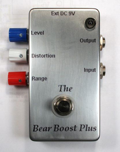
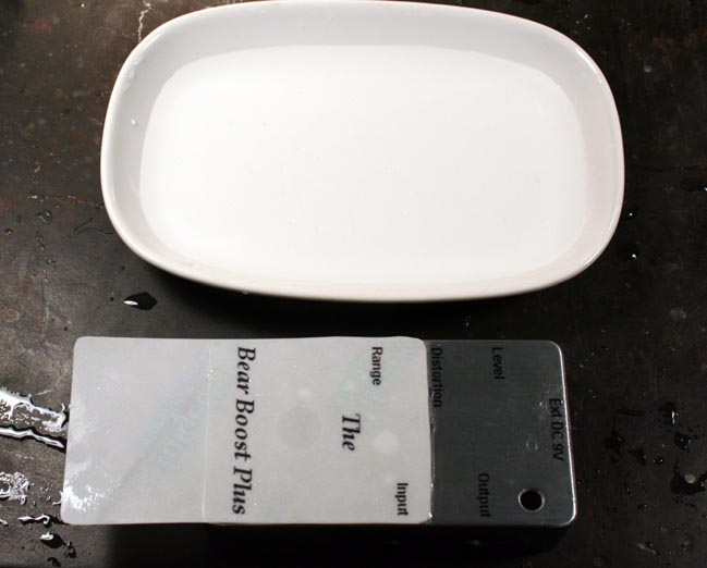
The Bear Boost Plus
© 2008 By Small Bear Electronics LLC
This article describes a hand-wired version of the Bear Boost Plus, and it includes a lot of technical detail meant for advanced DIYers. If you bought the kit, here's the beginner level instruction manual. The pedal comes out exactly the same, but the kit is based on a ready-to-solder PC board.
My amp in college days was one of those gray-and-silver Supros made by Valco that now command high prices as vintage gear. They delivered a glorious, bell-like, mid-range and good bass from two 12-inch Jensen speakers, but their only tone control was a treble-cut that wasn't very effective. This gave me incentive to start experimenting with treble boosts, and I came up with one at the time that was pretty gnarly. I tried duplicating it for this project and was only partly happy with the result. So, having gotten some experience in the last few years with Rangemaster and Fuzz Face clones, I decided to re-think the idea. The Bear Boost Plus is what emerged from the Cave. Here's the circuit:

The influences of the Fuzz Face and the Rangemaster will be obvious, and the pedal does pieces of both of those classics depending how the controls are set. With small input capacitors and R7 at minimum, you get a very sharp, biting treble boost. As you would expect, increasing the input capacitance gives you more mid-rangey, Rangemaster-ish funk. Raising the wiper of R7 off ground brings C10 more into the circuit, raises the effective gain and begins overdriving Q2. The germanium "soft-clipping" (the "Plus" of the effect) that results is very pleasing, and the ability to adjust its depth opens up lots of subtleties. Here are a few sound clips:
BasicTreble.wav RM-like.wav Bluesy.wav
To anticipate a question, Q2 does not have to be an expensive, medium- to high-gain device. The preamp stage Q1 boosts the input signal enough so that Q2 can be down as low as the 30s. It will still give excellent results as long it it isn't too leaky. R11 in my prototype is a single 100 meg resistor, but it can be 5 x 22 meg in series, or you can use R. G. Keen's Millenium Bypass circuit.
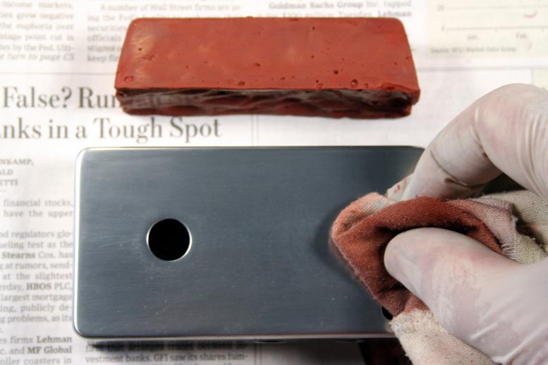
The construction is based on my three-knob shell, so you should start by referring to that article. Before you continue, you should have built the shell, disassembled it and done any painting, polishing, powder-coating or decorating that you want to. If you like the design idea in the lead pic, here is how to get that result:
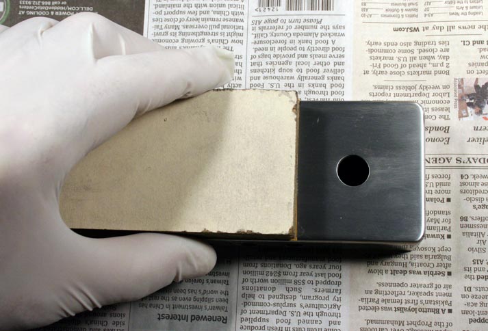
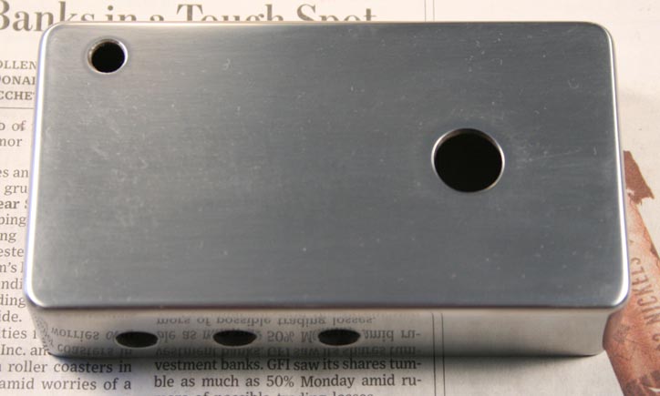
Wet-sand the enclosure starting with #220 grit carborundum paper. Then work your way through finer grits of 400, 600, 800, 1000, 1500 and 2000, and finally buff with jeweler's rouge. While it is a lot of work, the result is a very smooth, satin-like finish. Clean up thoroughly with acetone before decorating.
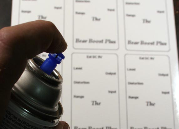
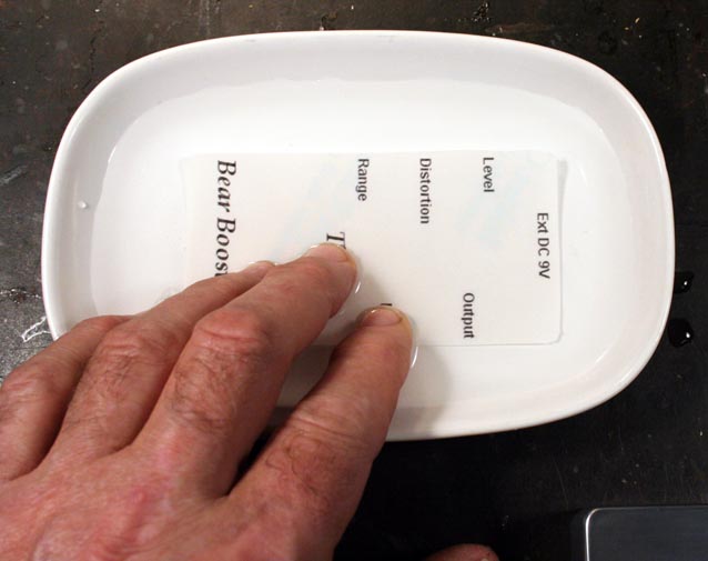
Here is a sheet of decals. I always put multiple images on one sheet in case my first try doesn't work. Always set your printer for the highest possible density. If you use inkjet decal stock, you need to waterproof the printed sheet with clear lacquer. "Shpritz" on a thin first coat, let harden about a half-hour, and then follow with two more thin coats a half-hour apart. Cut out one image with a sharp scissor. Soak the decal in warm water, and keep feeling gently for the point at which the plastic decal film releases from the paper carrier. When you feel the film beginning to release, remove the decal from the water. Lay the decal down on the surface of the enclosure, and carefully slide the backing paper out from under the film. When the film has been transferred, smooth it out and blot with a paper towel. You need to get All of the water out. These last two steps are a little tricky, but once you know how the material feels and works, you can get some remarkably good results repeatably.

Let the decal set for a few hours, and then seal it with multiple thin coats of clear lacquer.
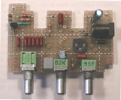
Now you can begin to stuff the board. When you were building the shell, I had you solder the center contacts of the pots in place in order to fix the position of the board. I suggest unsoldering those for now using a little solder wick and then re-installing when the rest of the components are in place.
Here is a layout drawing and parts list:
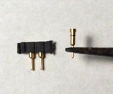
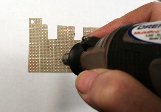
The nominal resistor values shown will produce a working pedal with any quiet, not-too-leaky germanium transistor having a gain of 40 to 60 measured by the "Bear-Bones" method. This being a DIY build, however, I know that many builders will want to be able to tweak the bias resistors and maybe swap FETS as well. To make this easier, I used individual pins taken from Mill-Max single-in-line socket material to create component "sockets." I like the result, and I can stock the unmounted pins if other people want them. The pics following show the idea. Using a #55 drill, bore out the hole where the pin is to go. That size is just right to leave part of the copper pad on the board for solder to bond to. Insert the pin and solder it in place. The resulting construction is almost like a rivet.
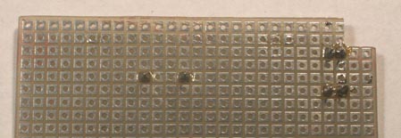
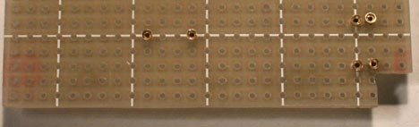
I'm not going into major detail on wiring the board, because you should not be building this way unless you have already done a basic build like the Tweak-O and so have some experience with perfboard construction. I suggest installing first all of the socket pins that you will want. Then follow with the resistors that you won't be tweaking, jumper, capacitors, diodes and transistor socket for Q2. Before installing the pots, add flea clips as tie points for the off-board leads. Install the pots and the DC jack before you start the under-board wiring. The left pic below is the stuffed board. As always when building on perfboard, I suggest using your multimeter to check your wiring for continuity and correctness as you work, and noting your progress with a highlighter.
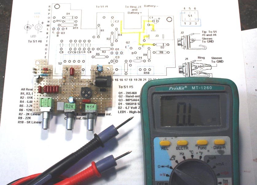
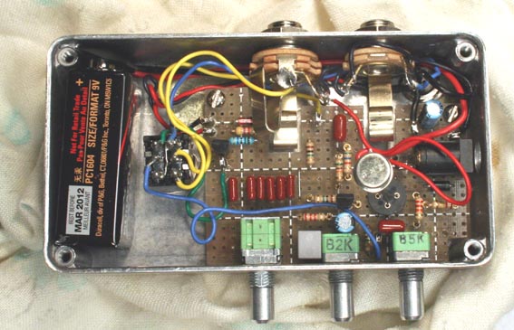
Finished under the board? On to final assembly! Install the LED bezel and LED, add connecting leads and insulate with heat shrink. Make sure that you know which is plus and which minus! Screw down the board and install jacks and stomp switch. Before doing the off-board wiring, plug in the resistors you want for initial testing. Here is the fully stuffed and installed board with a transistor inserted for initial testing and biasing. I rested the case on a soft cloth so that I wouldn't scratch the finish while poking around with a meter.
In starting to use the pedal, the first question you will probably have is: How come the distortion control doesn't work? It does, and you'll hear it come into play at the higher-capacitance settings of S2.
If It Doesn't Work
I built from the layout drawing above, and the model you see here worked right off the rip. I had forgotten a couple of connections to the LED driver circuit, but that was the extent of the debugging needed. Follow the usual procedures for finding problems when you are working from a known-good layout. I took a few voltage measurements that may be useful, though keep in mind that they will vary with the devices used for Q1 and Q2. I'm not sure how accurate my reading is on the base of Q2, because it's a very small voltage and my multimeter is only 10 meg input impedance.
| Q1 | Source | Gate | Drain |
| -1.45 | 0 | -4.59 | |
| Q2 | Collector | Base | Emitter |
| -7.02 | -155 mv. | -89 mv. |
The device on which I took these measurements (and which produced the sound clips) had leakage of 45 microamps, and a "Bear-Bones" adjusted gain of 42 at room temp. Since I am sure that someone will ask: I have not tried to build the Bear Boost Plus with an NPN device, but it should be very straightforward; reverse all polarities and use an n-channel JFET (2N5457 looks possible from the spec sheet) for Q1. I don't suggest trying to do the PNP version as negative ground; there are too many potential problems, and low-gain NPN germanium is neither hard to find, nor terribly expensive.
I must 'fess up: Part of my motivation for designing this pedal was finding a good vehicle for the thousands of germanium transistors in my stock that aren't "hot" enough for Fuzz Faces and such. But the result is so happily growly that I can say without reservation: Build one! The fact that the parts are cheep and readily available just makes enjoying the result that much sweeter. Happy Construction!
SD
smallbearelec@ix.netcom.com