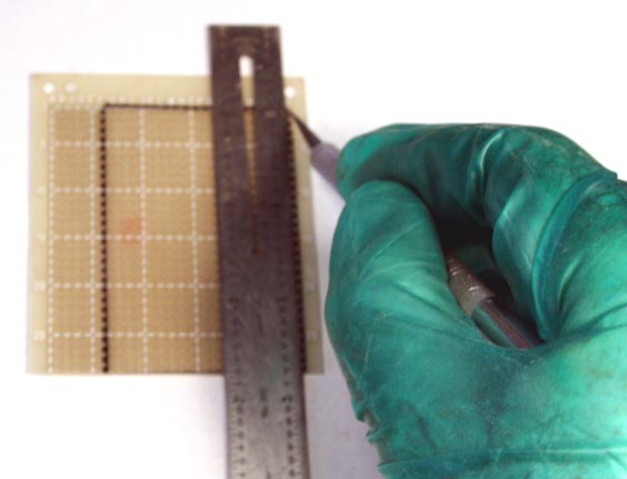
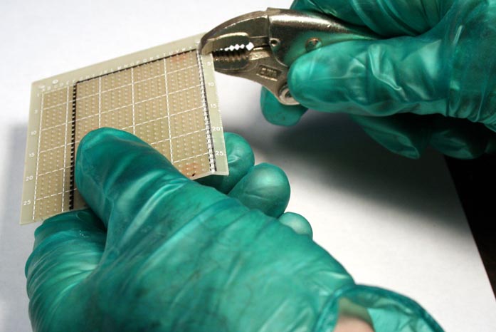
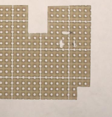
(IMORTANT NOTE: Machining epoxy-glass circuit board creates fiberglass dust, which is noxious stuff! When doing any tooling of the board, wear disposable gloves and a face mask!)
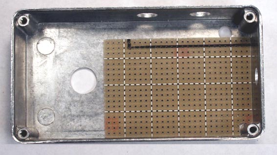
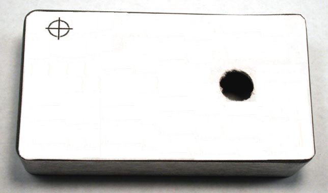
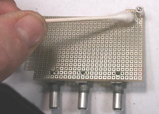
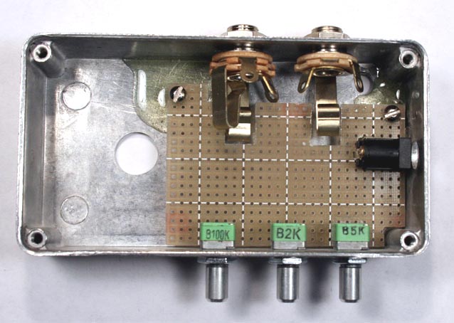
If you are using Alpha RD09 series pots, the contacts will go in the second row of holes in from the mounting panel. The center pin of the rightmost control should go in hole 5 from the right. The other two pots center on holes 12 and 20 respectively. Set the pots in place by hand to start, and eyeball the horizontal registration. If the registration is good as shown in the pic, you can proceed with fixing the position of the board. If the registration is off, you may be able to salvage the job with some filing.
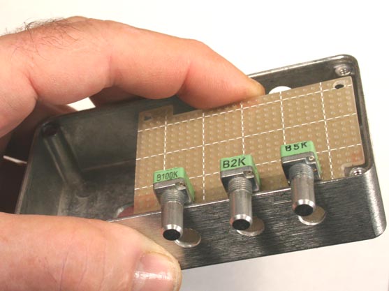
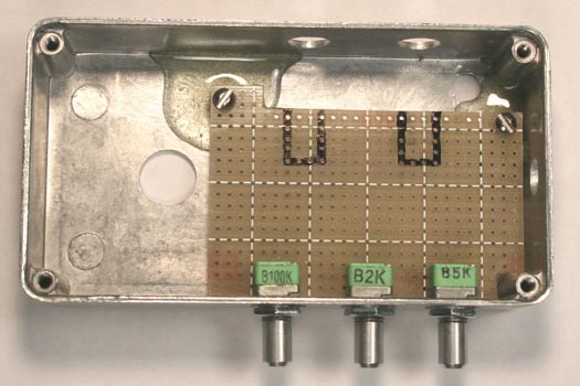
Making sure that the pins are in their correct holes and that the bottom of the control is flush to the board, solder in place the center contact of each pot. Slip the board in place, and scribe a mark where each mounting stud will rest.
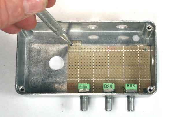
I used 1/8" studs in this build so that I would have use of every millimeter of board space. Screw a mounting stud and a 4-40 screw into each mounting hole. Again slip the board in place, screw washers and nuts finger-tight to the pots, and eyeball the vertical registration. You want the board to be as close as possible to exactly parallel with the floor of the enclosure. Depending on how precise your drilling was, you may or may not need to file the mounting holes slightly larger to achieve this.
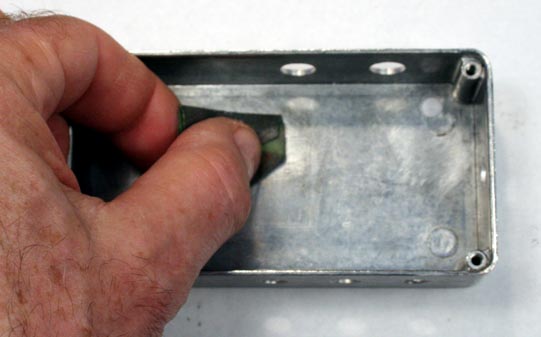
Once the registration is correct, remove the board from the enclosure. Clean the marked location of each stud with 220 grit carborundum paper and then wipe clean with acetone. Clean the studs with a Q-Tip wetted with acetone.
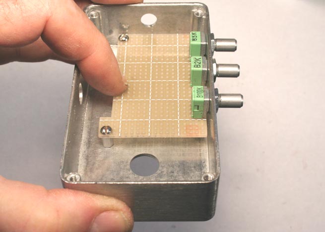
Mix a small amount of quick-setting epoxy cement and apply a small bead to the mounting location of each stud. Slip the board in place carefully. Slip the washers and nuts on the pots, but finger-tight only. Let the epoxy cure for several hours.
When the epoxy has fully cured, remove the screws from the board and the washers and nuts from the pots. Lift the board out gently and reinforce the mounting of the studs with more epoxy. Again, let the epoxy cure fully before proceeding.
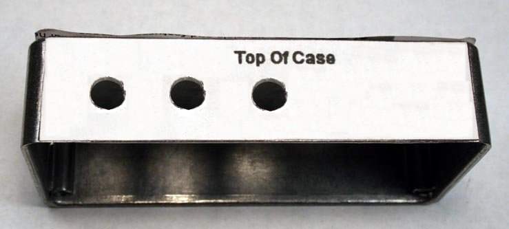
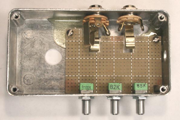
Use a Sharpie to mark the cutouts for the flanges of the jacks. I used a small hacksaw to make the vertical cuts and broke off the inside piece with a locking-grip plier. If you cut with a Dremel tool, WEAR GOGGLES!
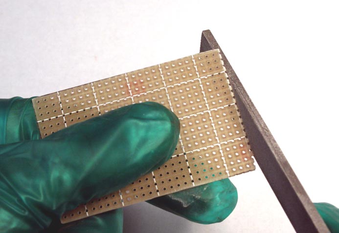
Use a flat file to smooth the edges of the slots. Reassemble the shell, install the jacks, and be sure that the flanges move freely when a plug is inserted.
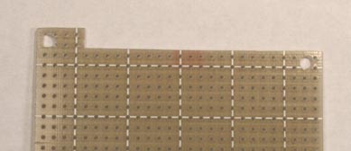
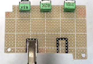
The last step is cutting slots in the board for the contacts of the power jack so that you know it will be positioned correctly at final assembly. You can do this by boring successive holes with a #63 drill, though a diamond burr in a Dremel handpiece makes it easier to do a neater job.
Your shell is finished and is ready for painting and decorating! I hope you found this article useful, and I welcome comments and suggestions at smallbearelec@ix.netcom.com.