How To Make A PC Board By The Positive Photo Process
By Steve Daniels, Small Bear Electronics LLC
© 2010 By Small Bear Electronics LLC
Making printed circuit boards is a necessary skill for being able to build electronic gear above a very simple level. This article describes a set of techniques, tools, and materials used to turn an image file of a circuit pattern into a finished board. A positive of the pattern is exposed onto a light-sensitized copper-clad blank. The blank is then developed to remove the exposed photo-resist and then excess copper is etched off. This photographic process is typical of the way PC boards are made industrially. It has long been available for DIY, but it has had a reputation for being a little temperamental and needing special equipment and chemicals. With some experimenting, I have reduced the complexity and made the process fairly easy and inexpensive to replicate at home. While my audience is specifically DIYers who want to build guitar stompboxes, the techniques are applicable to many other devices and designs.
I do not cover in this article creating your own printed-circuit patterns; that's a much more involved subject, and, if you are interested, you should seek references written by experienced designers. I presume here that you have either drawn out a pattern that you want to make into a board, or, more likely, that you have a jpg or pdf of an actual-size pattern from an on-line source that you want to transfer to copper.
Most of the tools and materials shown are available as a kit from my Stock List, but you don't have to use exactly the ones I show. Locally-purchased equivalents may be perfectly acceptable, and on-line resources like the Stompbox Forum often discuss alternates and work-arounds. That said, the items I provide are top-quality, professional-grade and thoroughly tested; they make it much easier to produce a good board on the first try.
What You Need:
This is a list of basics, and I'll give some suggestions at the end for alternates and "nice-to-haves".
Photo-sensitized, positive-resist, copper-clad blank circuit board
The best base material is FR-4, which is a laminate of fiberglass and epoxy resin. Other composites of phenolic, epoxy resin, cellulose and fiberglass are also used. Photo-sensitized stock is also made with negative resist, but it's a different chemistry. The method described here can be adapted for that, but I will not treat it in detail.
Inkjet-compatible Transparency Stock
The pattern is printed onto this as though making an overhead. The resulting "positive" is used to expose the light-sensitive surface of the circuit board. I used address-label stock in earlier experiments, and that can be made to work. However, it is not fully transparent; in my experience, the lack of full contrast makes the exposure time too critical. Standard transparency stock like Avery # 5277 is fine if you use a contact printer or even a piece of glass to hold the positive tight to the board. Still better is clear transparency material that has adhesive on one side, like Avery # 53212 Window Decal Stock. The latter often has to be mail-ordered, so suitable stock is part of my kit and also available separately on the Stock List.
Double-sided Scotch Tape
I use this for setting up the printing of a transparency.
Marking Pen or Liquid Resist Ink
You need one of these for filling any small voids left after transferring a pattern. A Sharpie Permanent marker will do, but a purpose-made industrial marking pen is preferable.
Developer
This is available pre-mixed from distributors, but it's unnecessarily expensive. It can be made (with appropriate care) from lye purchased at the supermarket. I'll discuss this further later.
Etchant
The most commonly used chemical is Ferric Chloride. It is available pre-mixed, or as a powder that is mixed with water. Many people have come to prefer Ammonium or Sodium Persulfate for etching, because it is a clear solution; this makes it easier to follow the progress. However, Persulfate solution is not stable, so it must be prepared in small batches as needed. My basic directions will use Ferric Chloride, but I will include notes on using Sodium Persulfate.
Etching and Developing Trays
Small glass, ceramic or rigid plastic (polystyrene, polyethylene or Lucite) trays, large enough to hold the board with room around it to agitate, and an inch or so deep.
Ruler
You'll want one for measuring pieces of board when cutting to size, and other planning jobs.
X-acto or similar Knife
Used to scribe fine lines on the copper in doing layout, also for cutting a board to size by the "score-and-snap" method.
Wire Number Drills
These are very fine twist drills for making the holes for component leads. The most commonly used sizes are #59 (.040") through #63 (.037").
Carborundum Paper
For deburring the edges of a freshly cut board. I use 220 grit.
Solvent
Acetone or nail-polish remover for stripping resist from a finished board.
Alternates and "Nice-To-Haves"
|
|
|
|
What You Get In The Kit
Two pieces of FR-4 positive photo-sensitized board, each 3" x 5"
One 8 1/2" x 11" sheet of adhesive transparency stock
A Dykem Action 33 marking pen
A plastic etching tray, 4 3/8" x 5 3/4"
A 6" steel rule
An X-acto-type knife with a soft-grip handle
Two #60 twist drills
One 4 1/2" x 5 1/2" sheet of #220 grit carborundum paper
A pair of plastic forceps
A 6-ounce bottle of Ferric Chloride solution
A Design To Learn With
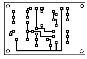
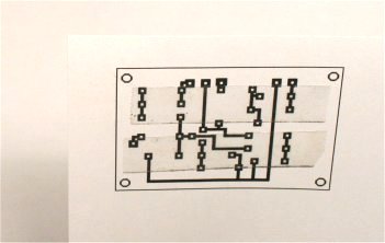
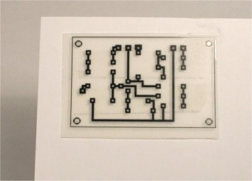
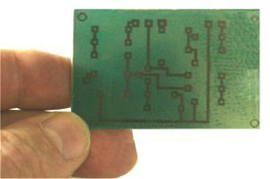
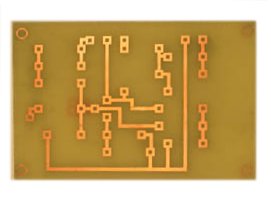
Many people have built Joe Davisson's Tweak-O as a first pedal. I have long offered it as a kit for building on pad-per-hole perfboard, and it was easy to turn that layout into a PC board pattern. You can download it as a .pdf from this link, and it looks like this:
The pattern above is exactly as you will see it on the solder side of the finished board. The finished board will have exactly the same outside dimensions as the perfboard version, and it can be used as a drop-in replacement if you want to build a Tweak-O with it. I'll say more about this when we are done.
Cutting A Blank To Size
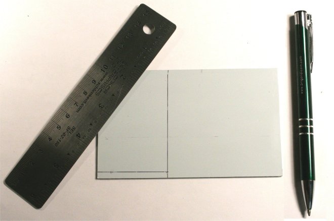
The first job is to cut down a piece of PC board stock to the size of the board we want to make. The Tweak-O board is 2 13/16"long by 1 7/8" wide. I'll show you a score-and-snap first and then address alternate methods.
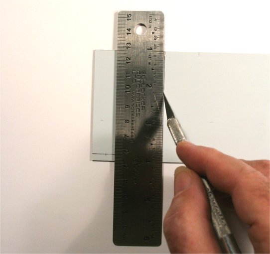
Photo-sensitized stock is reasonably tolerant of normal room illumination, both because it exposes slowly and because the sensitive surface is covered by an opaque, self-adhesive film. Still, don't shine a strong light on it while tooling. Using a steel rule and a ballpoint pen, mark the size of the piece to be cut on the plastic film. Then use a knife to score from top to bottom over the line on which you will snap. Do this at least six or seven times times so that you cut through the copper layer.
Fiberglass fragments and dust are noxious, so I wear disposable gloves and a filter mask when I do any machining of FR-4.
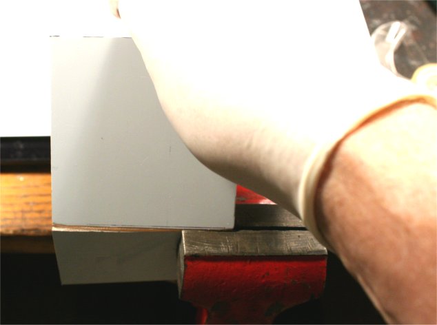
Set the piece up to snap. I have done this successfully by wedging in a door frame, but the job is much easier if you have a vise, or can get access to one. Clamp the piece on the score line as shown here. If the jaws of the vise are serrated, use a thin piece of wood on each side to protect the surface of the board.
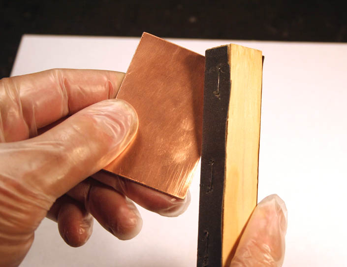
Snap the board by applying strong, steady pressure near the top edge. My vise is not deep enough to accommodate the full length of the score line, but the piece still broke cleanly enough. I straightened and deburred the cut edge with a flat file. You can also make a tool for this purpose by stapling a piece of #220 sandpaper or carborundum paper to a small piece of soft wood. The right-hand pic shows this on a piece of ordinary copper-clad board.
Now repeat the whole process on the other edge.
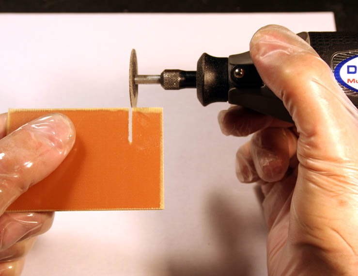
There are other ways to cut FR-4 in a home shop. I have used a hacksaw on regular copper-clad, but I did not like it for the photo-sensitized stock; too easy to damage the protective film...YMMV. A cutoff wheel on a Dremel tool works very well on both regular and photo-sensitized stock. However, my standard warning applies: Be aware that these attachments are inherently dangerous and subject to shattering without warning; eye protection is an absolute must!
The board is ready to receive a pattern. Store in its light-tight bag until you are ready to expose it.
Making A Positive - Printing To Transparency Stock
While it is possible to run a whole sheet of transparency stock through an inkjet printer more than once, I prefer to cut a small piece to size and use a piece of plain paper as a "carrier."
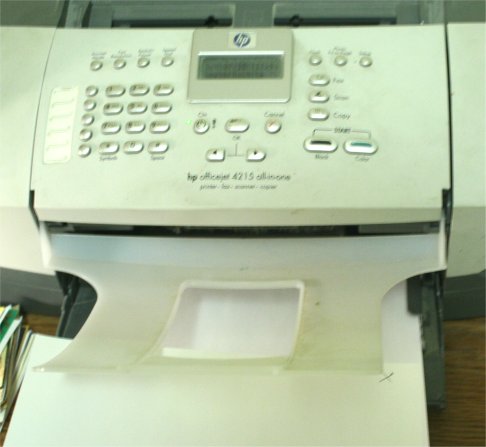
Mark one edge of a piece of plain paper, load in your printer and print the positive image to it.
Now that you know where the printer will place the image (and so how to orient the paper in the printer tray), you can use this same sheet as a "carrier" for a small piece of the transfer film. Lay a couple of strips of double-sided tape across the printed image:
Cut out a piece of the transparency film that is slightly larger than the image. Lay this down carefully over the image with the image side facing up. Press the film down gently with a clean sheet of paper, not bare fingers, so you are assured of good adhesion.
You are ready to print for real. Load the carrier into the paper tray, using the mark that you made when you started to make sure that the sheet is oriented correctly. Set your printer for Transparency Stock and the highest print density the software will allow. Print! If you did everything right, you have a positive.
Gently lift the positive off the carrier sheet and trim to size with a sharp scissor. You are ready to expose and develop your board.
Making The Developer
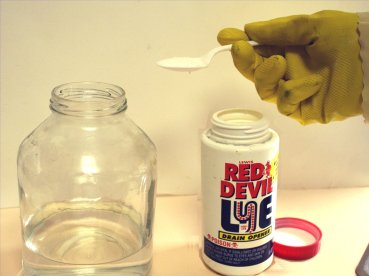
Have this ready before you expose the board. Developer for positive photo resist is a 10% solution of Sodium Hydroxide, which can be found in any supermarket as lye. This stuff is extremely dangerous if misused! Read the precautions on the container and follow them! Wear goggles and rubber gloves when working with lye.
Find a clean, one-quart glass jar with a wide mouth and a secure screw cap. Fill with one pint (16 ounces) of tap water. Using a plastic spoon, measure in one level teaspoon of lye. DO NOT DO THIS IN REVERSE! Adding water to dry Sodium Hydroxide can cause spattering that verges on explosive!
Using a wood or plastic rod, stir the solution until the chemical dissolves completely. You now have enough developer for dozens of boards. It will keep indefinitely at room temp. However, please label it carefully and store out of reach of children!!
Set up a small glass, plastic or ceramic tray that is large and deep enough to hold the board with some room to agitate. Fill with enough developer to cover the board.
Exposing The Board
The process is tolerant enough that I did not find it necessary to use a darkroom. I did all of the steps you see below in normal kitchen room light, working quickly but carefully. Of course, I kept the board in its protective bag until I was ready to expose it.
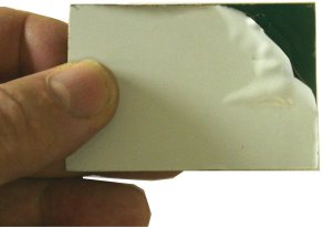
Peel the positive away from its backing paper and set it down on a dry surface with the adhesive side up. Remove the protective plastic film from the board.
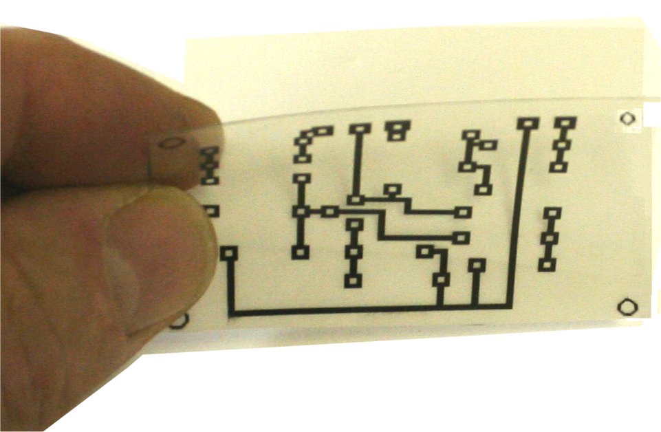
Carefully, apply the positive to the sensitized surface. Line it up as closely as possible with the corners. If you don't get the registration just right on the first try, don't panic; I have found that the adhesive can be peeled off and then re-applied without damaging the resist. Once the positive is positioned correctly, gently smooth it down.
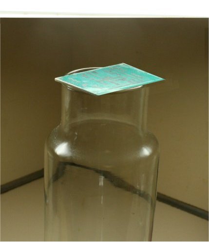
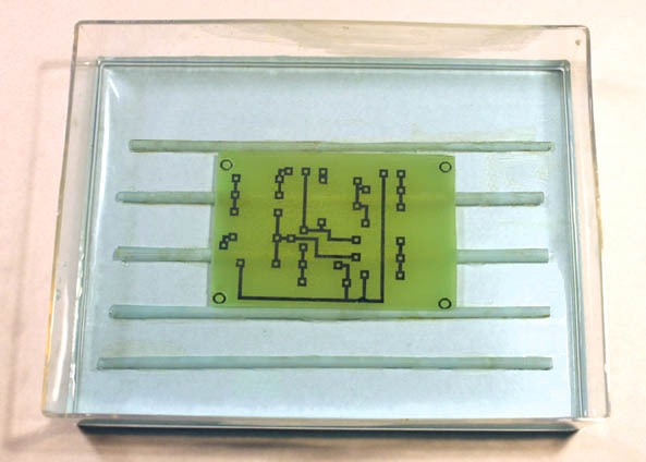
Here I am in our kitchen. There was an available 15-watt fluorescent tube over the sink, and I set up a jar as a support to hold the board about two inches away. Exposure time was 5 minutes.
YMMV! While the process is tolerant as I noted earlier, you may have to experiment with a small piece of stock and small test print to determine the right exposure time for your environment. Once the light intensity and time are established, however, I have found the process very repeatable.
Turn off the light at the end of the exposure time. Peel off the positive slowly and carefully, and immediately slide the board into the developer. Rock the tray gently. The exposed resist will dissolve in a couple of minutes and the solution will turn a light Prussian Blue.
When the pattern is sharp and clear and the exposed resist is all gone, rinse the board thoroughly with clean water. Don't handle the board with bare fingers till you have done this; while the developer is not caustic at this concentration, you should still treat it with respect.
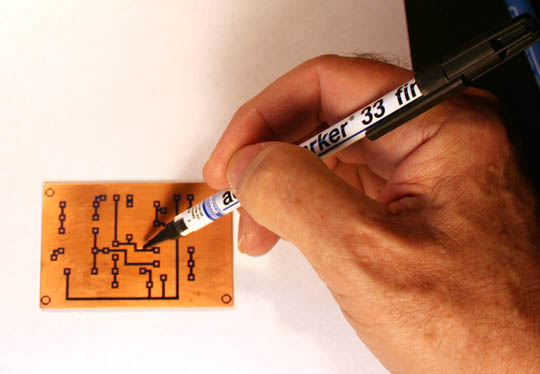
Small imperfections can be touched up with the marking pen.
Now that you have the pattern defined on copper, the board is ready to etch.
Etching The Board Using Ferric Chloride
My kit comes with a plastic tray (actually half of a polystyrene box,) but any similar-sized vessel of plastic, rubber, glass or ceramic will also do. If you find a small one that already has ribs on the bottom, grab it. I could not, so I added ribs to my plastic one by slicing a few cocktail straws in half and gluing them in place with quick-setting epoxy:
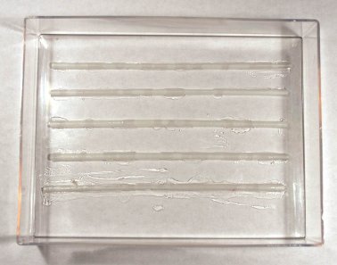
The ribs make it easy to get a pair of forceps under the board to lift it out of the bath.
Most references I have seen recommend warming Ferric Chloride (usually by putting the open bottle in a bath of hot water) in order to speed the process and avoid undercutting the resist. It's a good idea, though not necessary in my experience for small boards that don't have fine lines.
Note that while Ferric Chloride is not corrosive to skin, it will badly stain both skin and fabric. Take care when pouring, and when removing the board.
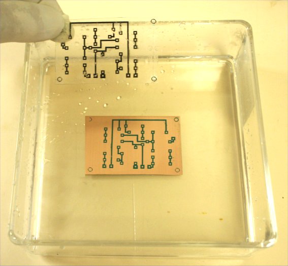
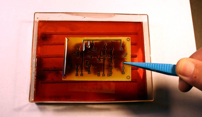
Lay the board in the tray and pour in enough Ferric Chloride to just cover it. Agitate the tank every few minutes, and lift the board out periodically to check progress of the etch:
Etching Using Sodium Persulfate
I had used this material successfully to etch toner transfers done with Press N' Peel. The directions on the label suggest a dilution of one-half pound by weight to one gallon of water, which I translated to one-quarter ounce by weight (about a rounded teaspoon by volume) per four ounces for making a small batch. I used the hottest water I could get from my tap and stirred the powder in with a plastic spoon till it dissolved completely. One caution: When diluting Sodium Persulfate, never add water to a mass of the powder; always add the powder to the water. Doing it the wrong way can result in spattering that verges on explosive.
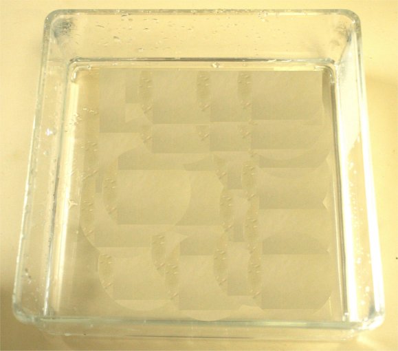
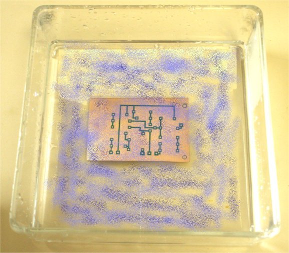
Use the solution exactly you would Ferric Chloride. I have found that leaving the etching tray underneath a 60-watt desk lamp heats the solution enough to speed the process some. Within 15 minutes, the solution will start to go light blue as the copper on the board starts turning to Copper Sulfate. The process takes a couple of hours, much longer than Ferric Chloride, but it ultimately works well. It's very easy to see when etching is complete:
When the board is fully etched, rinse it thoroughly in clean water. Then strip the resist with acetone:
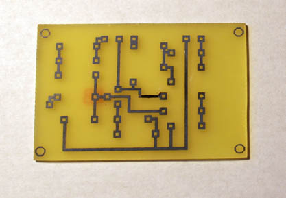
The board is ready to drill and stuff. Just to make sure that I hadn't made any mistakes, I went all the way--drilled it, stuffed, wired straight through and tested:
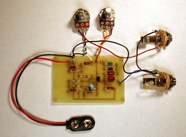
It works! As I noted earlier, this board can be dropped right into the Tweak-O design in Projects, should you wish to build this way.
I hope that you found this introduction useful, and that it encourages you to try making more complex PC boards. Please direct any questions or comments to smallbearelec@ix.netcom.com.