How To Make A Basic PC Board By Direct Etching
By Steve Daniels, Small Bear Electronics LLC
© 2011 By Small Bear Electronics LLC
Making printed circuit boards is a necessary skill for being able to build electronic gear above a very simple level. This article describes a set of techniques, tools, and materials used to turn a copy of a circuit pattern into a finished board by transferring the pattern onto a copper-clad blank, and then etching off the excess copper. This is direct etching, as opposed to the photographic techniques used in other processes. While my audience is specifically DIYers who want to build guitar stompboxes, the techniques are applicable to many other devices and designs.
I do not cover creating your own printed-circuit patterns; that's a much more involved subject, and, if you are interested, you should seek references written by experienced designers. I presume here that you have either drawn out a pattern that you want to make into a board, or, more likely, that you have a jpeg or pdf of an actual-size pattern from an on-line source that you want to transfer to copper using Press N' Peel film.
Most of the tools and materials shown are available as a kit from my Stock List, but you don't have to use exactly the ones I show. Locally-purchased equivalents may be perfectly acceptable, and on-line resources like the Stompbox Forum often discuss alternates and work-arounds. That said, the items I provide are top-quality, professional-grade and thoroughly tested; they make it much easier to produce a good board on the first try.
What You Need:
This is a list of basics, and I'll give some suggestions at the end for alternates and "nice-to-haves".
Copper-clad blank circuit board
The best base material is FR-4, which is a laminate of fiberglass and epoxy resin. Other composites of phenolic, epoxy resin, cellulose and fiberglass are also used.
Transfer Film
There are several brands out there. You print your design on it using a laser printer or photocopier, and then iron the pattern onto copper. I have long used Techniks Press N' Peel (P-n-P).
Please note: P-n-P will not work with inkjet printers. You must have access to a laser printer or photocopier. Also, compatibility problems have been reported with the toner used in Brother printers.
Double-sided Scotch Tape
I use this for setting up the printing of a P-n-P transfer.
Marking Pen or Liquid Resist Ink
You need one of these for filling any small voids left after transferring a pattern. A Sharpie Permanent marker will do, but a purpose-made industrial marking pen is preferable.
Etchant
The most commonly used chemical is Ferric Chloride. It is available pre-mixed, or as a powder that is mixed with water. Many people have come to prefer Ammonium or Sodium Persulfate for etching, because it is a clear solution; this makes it easier to follow the progress. However, Persulfate solution is not stable, so it must be prepared in small batches as needed. My basic directions will use Ferric Chloride, but I will include notes on using Sodium Persulfate.
Etching Tray
A small glass, rubber, ceramic or rigid plastic (polystyrene, polyethylene or Lucite) tray, large enough to hold the board with room around it to agitate, and an inch or so deep.
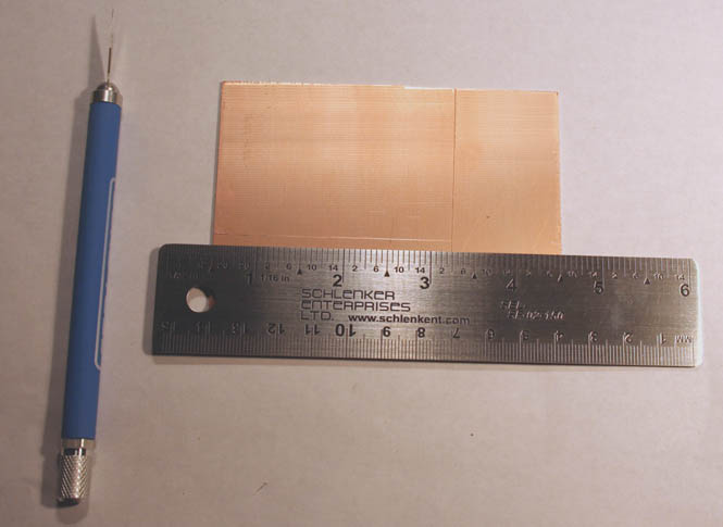
Ruler
You'll want one for measuring pieces of board when cutting to size, and other planning jobs.
X-acto or similar Knife
Used to scribe fine lines on the copper in doing layout, also for cutting a board to size by the "score-and-snap" method.
Wire Number Drills
These are very fine twist drills for making the holes for component leads. The most commonly used sizes are #59 (.040") through #63 (.037").
Carborundum Paper
For deburring the edges of a freshly cut board. I use 220 grit.
ScotchBrite Pads
Used with a little BonAmi or similar abrasive cleanser for cleaning the copper surface.
Solvent
Acetone or nail-polish remover for stripping resist from a finished board.
Alternates and "Nice-To-Haves"
|
|
|
|
|
What You Get In The Kit
Two pieces of FR-4 blank board, each 3" x 4"
One 8 1/2" x 11" sheet of Press N' Peel
A Dykem Action 33 marking pen
A plastic etching tray, 4 3/8" x 5 3/4"
A 6" steel rule
An X-acto-type knife with a soft-grip handle
Two #60 twist drills
One 4 1/2" x 5 1/2" sheet of #220 grit carborundum paper
A Scotchbrite pad
A pair of plastic forceps
A 6-ounce bottle of Ferric Chloride solution
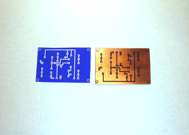
A Design To Learn With
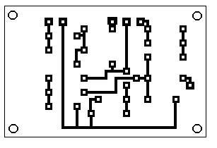
Many people have built Joe Davisson's Tweak-O as a first pedal. I have long offered it as a kit for building on pad-per-hole perfboard, and it was easy to turn that layout into a PC board pattern. You can download it as a .pdf from this link, and it looks like this:
The pattern is in "X-ray" view, meaning that this is how it appears if you are looking at it through the component side of the board. The finished board will have exactly the same outside dimensions as the perfboard version, and it can be used as a drop-in replacement if you want to build a Tweak-O with it. I'll say more about this when we are done.
Cutting A Blank To Size
Our first job is to cut down a piece of PC board stock to the size of the board we want to make. The Tweak-O board is 2 13/16"long by 1 7/8" wide. I'll show you a score-and-snap first and then address alternate methods.
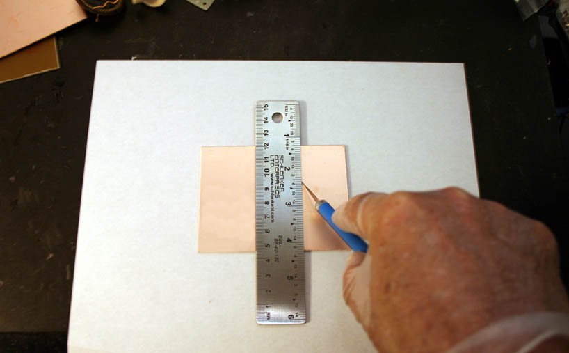
Using a steel rule and knife, scribe the size of the piece to be cut onto the copper side:
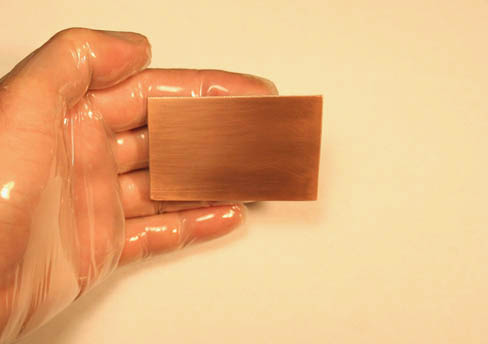
Fiberglass fragments and dust are noxious, so I wear disposable gloves and a filter mask when I do any machining of FR-4. Score the board several times from top to bottom on the edge that you are going to snap. You want to score straight, and get through the copper to the base material:
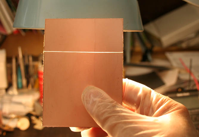
Holding the board up to a light after a few strokes will tell you whether you have cut through:
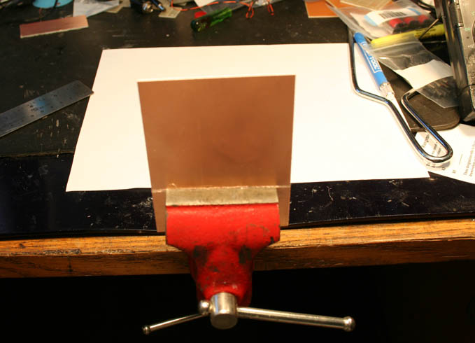
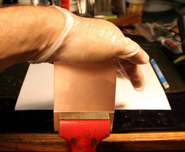
Now set the piece up to snap. I have done this successfully by wedging in a door frame, but the job is much easier if you have a vise, or can get access to one. Clamp the piece on the score line as shown here. If the jaws of the vise are serrated, use a thin piece of wood on each side to protect the surface of the board:
Snap the board by applying strong, steady pressure near the top edge:
Now repeat the whole process on the other edge.
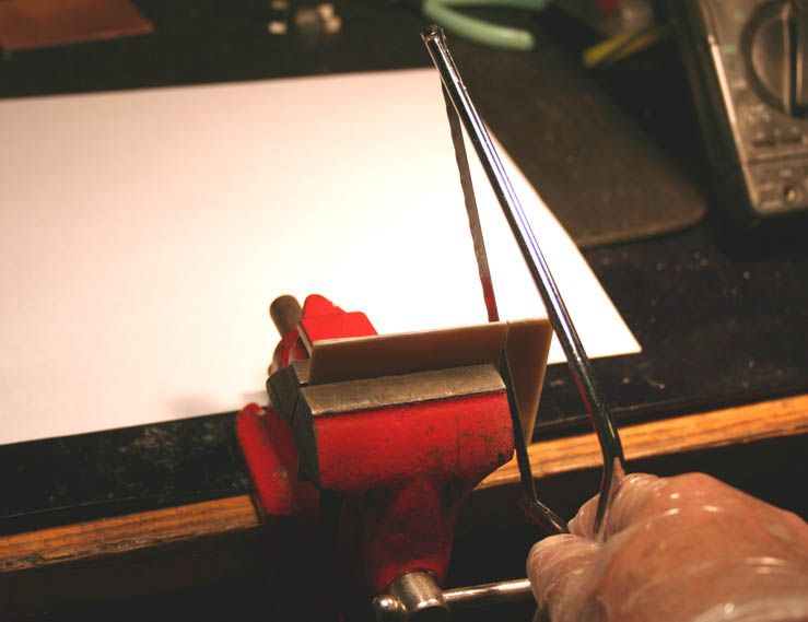
There are other ways to cut FR-4 in a home shop. A hacksaw will work, either standard-size or one of the many miniature types like the one in this pic. Use the finest blade that you can find, and clamp the board in a vise to keep it stable:
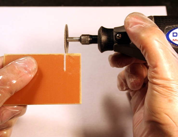
A cutoff wheel on a Dremel tool also works very well. However, be aware that these attachments are inherently dangerous and subject to shattering without warning; eye protection is an absolute must!
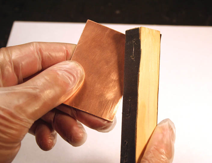
Once you have snapped or cut the board to size, you need to deburr and smooth its edges, especially on the copper side; if the edges of the copper cladding aren't perfectly flat, they will prevent your iron from properly contacting the metal surface. For this job, make a sanding block by stapling a piece of #220 sandpaper or carborundum paper to a small piece of soft wood. Smooth each edge of the board, top and bottom:
Cleaning The Blank
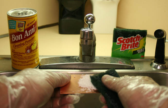
The copper surface has to be scrupulously cleaned in order for resist to adhere to it properly. If the ScotchBrite pad is new, soften it a little by wetting thoroughly with warm water and squeezing it out a few times. Make a thin paste of BonAmi or a similar cleanser, and scrub the copper gently till it is uniformly shiny all over:
Rinse off every trace of the cleanser and dry the board with a clean, lint-free paper towel. From this point on, do not touch the surface of the copper with bare fingers! The board is ready to receive a pattern:
Making A Toner Transfer - Printing To Press-n-Peel Film
First, a note: Many references, both on-line and print, detail this process. The ones I have seen agree in general outline and differ in details. Before you write to me saying that "this source says to do it a different way!," I'm letting you know that those other references may well be fine. As for me, I have created many boards using the procedures I show here, and I know that they work.
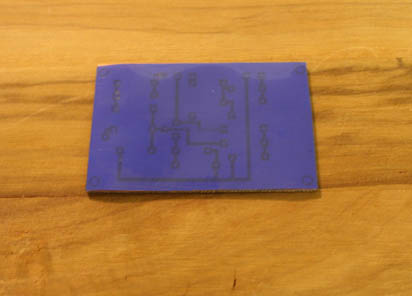
Press-n-Peel (P-n-P) film comes as an 8 1/2" by 11" sheet. It has a shiny side, and a dull, emulsion side. We will print the PC board pattern to the emulsion side. The toner (actually a mixture of plastic and carbon black) from the laser printer or photocopier will stick to the emulsion, so the pattern transfers to the P-n-P. Then we will iron the pattern from the film onto the copper, in the same way you might iron a design onto a T-shirt.
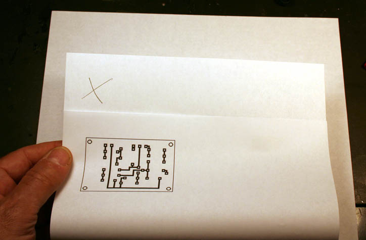
First, print the pattern to a piece of plain paper. If you are using an unfamiliar printer, open the paper tray and mark a corner of the top sheet before sending the file to print:
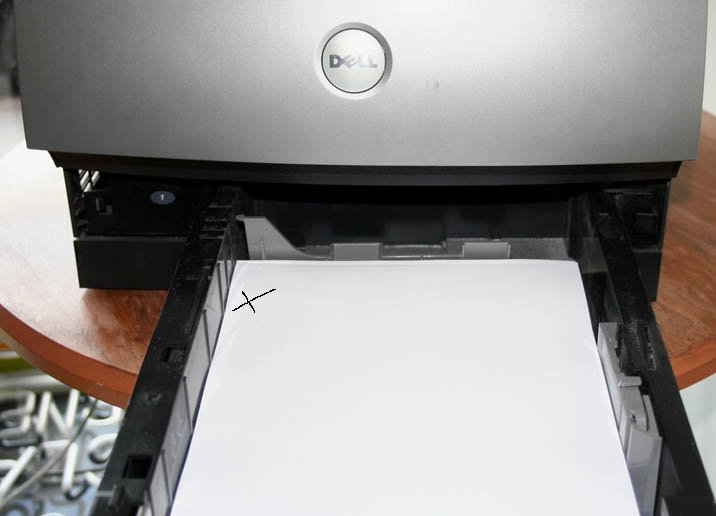
Looking at the result, it's clear that this printer turns the paper over when it prints. Also, the top of the printed image is at the edge of the paper that is at the front of the printer.
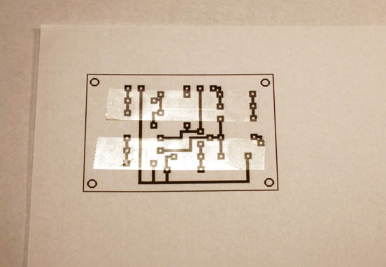
Now that you know where the printer will place the image (and so how to orient the paper in the printer tray), you can use this same sheet as a "carrier" for a small piece of the transfer film. Lay a couple of strips of double-sided Scotch tape across the printed image:
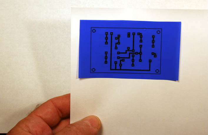
Cut out a piece of P-n-P that is slightly larger than the image. Lay this down carefully over the image with the dull (emulsion) side facing up. Press the film down gently with a clean sheet of paper, not bare fingers, so you are assured of good adhesion:
You are ready to print for real. Load the sheet into the printer paper tray, using the mark that you made when you started to make sure that the sheet is oriented correctly. Print! If you did everything right, you have a toner transfer:
Gently lift the transfer off the carrier sheet, place the emulsion side down on a clean area of the paper, and carefully peel away the tape. The knife may be helpful in getting started:
With a sharp scissor, trim the toner transfer to size:
I usually make several copies in case I screw up the ironing...
To anticipate a couple of questions: I have never had a problem with paper jams when using this technique. I have not tried it with a photocopier, but I expect that it would work.
Ready To Iron
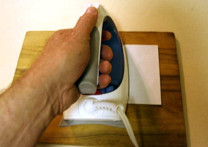
Set up your ironing board, and have available a piece of hard sheet material to use as a base under the blank (I use a wooden board.) Set the temperature control and warm up your iron. Unfortunately, every iron is different, and the "right" setting will vary from unit to unit. Techniks recommends using the Polyester setting.
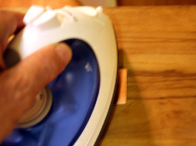
Francisco Peña, and others, suggest briefly pre-heating the board before applying the toner transfer. I found this helpful for getting good adhesion. However, I noticed that if I pre-heated very long, the transfer stuck to the board almost immediately on contact and left me no leeway to center it. I did the pre-heat by holding the iron about an inch above the board for about a minute. This gave me a good result--YMMV:
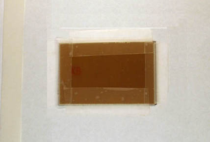
Lay the toner transfer onto the copper, lining up the edges carefully. The Techniks instructions say to follow with a piece of plain paper between the toner transfer and the iron "to reduce friction". I have tried this and do find it helpful:
I know you thought we'd never get here...OK, Iron! Slowly, back and forth, and it doesn't take much pressure. Time? It depends on your iron, as noted, but you will be able to go back and try again if you are not happy with the result. Small boards don't usually need more than 90 seconds:
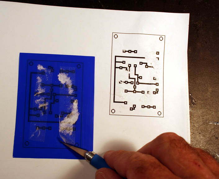
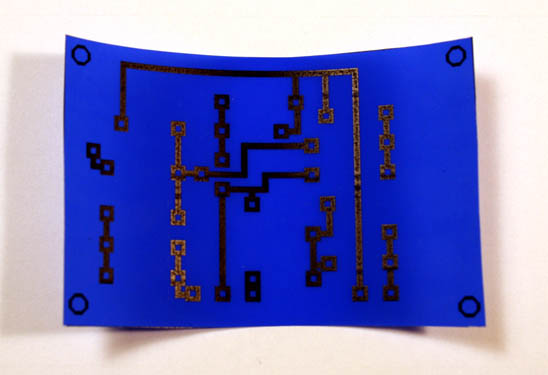
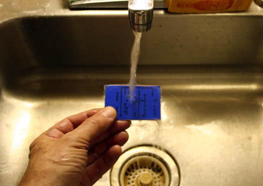
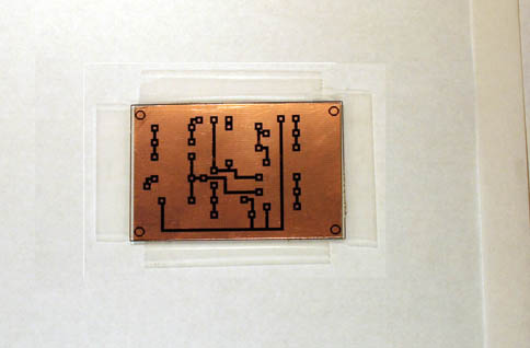
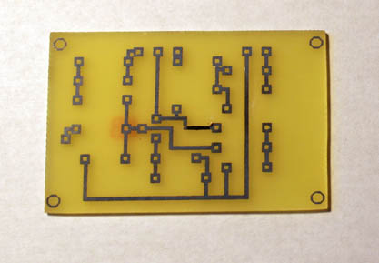
Quench the board under cold running water to bring it back to room temp, and peel the film away gently:
If your transfer has too many voids or otherwise didn't come out well, just remove the pattern by rubbing with a clean rag wetted with acetone and do the transfer again.
Note: Acetone is volatile and extremely flammable. NEVER leave a container of acetone lying open! Especially if there is a source of heat or sparks in the area, you are asking for fire or explosion!
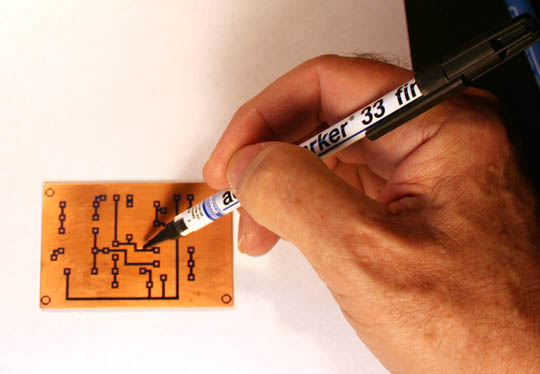
Small voids can be touched up with the marking pen:
Layout Using Dry Transfers
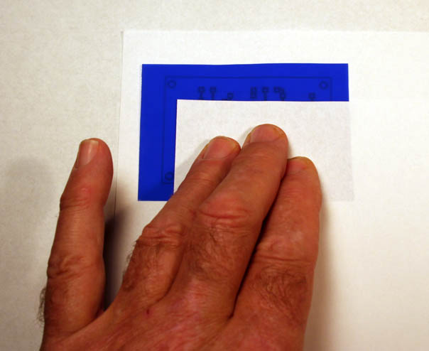
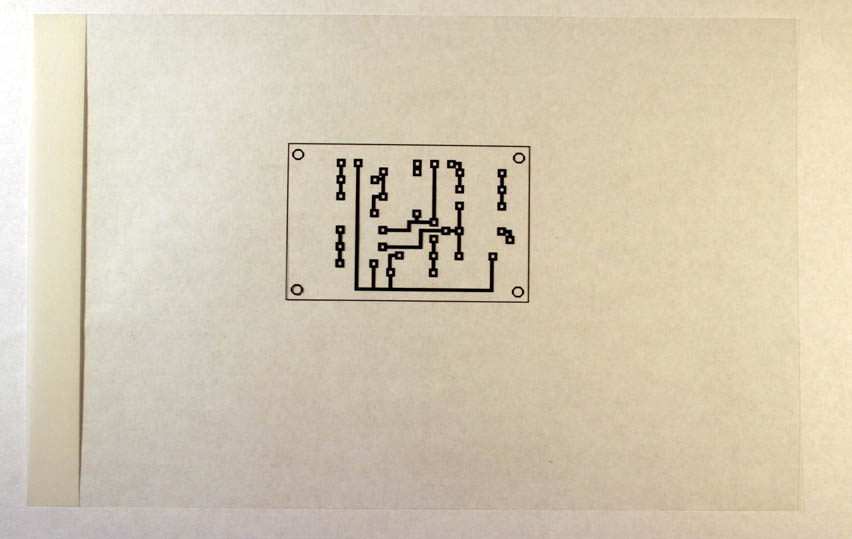
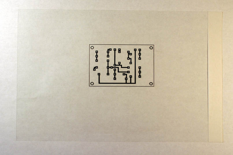
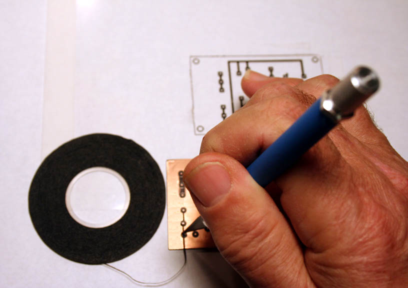
Call me impossibly old-fashioned...I think it's still useful to know how to lay out a circuit pattern by hand. Say that you don't have access to a laser printer or photocopier and you still want to make this board. OK, the layout pattern we have is in "X-Ray" view. We need to mirror the image, so as to see it exactly as we will lay it out on the copper. Pre-personal computers, I would create this kind of artwork by laying it out on tracing paper using resist tape, adhesive donuts and dry transfers. But now I bow to modernity by printing to a piece of inkjet-compatible transparency stock and then turning the sheet over:
If you can't find transparency stock, use software to mirror (some programs say "horizontally flip") the image and then print to tracing paper, or even plain paper. If your pattern is a jpg, most graphics programs (like Paintshop) will mirror the image. If it's a pdf, there are shareware programs (I have used Ghostscript) that will convert pdf format to jpg so that you can do the mirror.
After you print, leave several hours for the ink to dry thoroughly!
Using ordinary scotch tape, tape the board to the side of the sheet that carries the printed image. Then flip over:
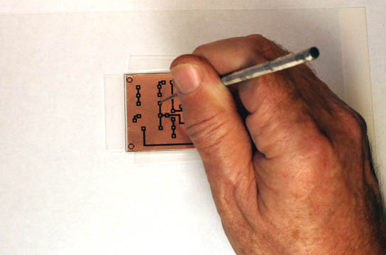
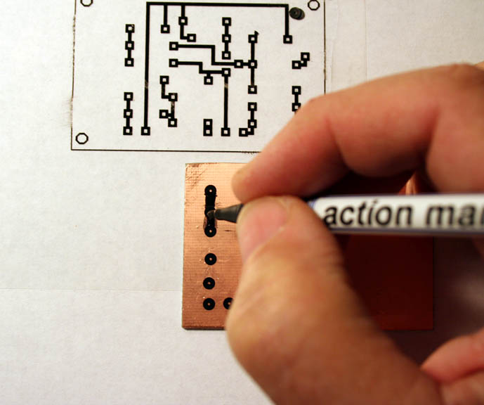
Using an awl, pick or scribe, make an indentation at the center of each pad:
Once you have marked a location on the copper for every pad, you can remove the board from the artwork. Keep the artwork (or a copy) near to hand for use later as a guide to connecting the pads:
Dry-transfer donuts come in many sizes. The ones I like for most common resistors, caps and transistors are 1/8" in diameter, and they come on carrier sheets. I typically cut off a row for easier handling. Locate the center hole of a donut over an indentaation, and rub it in place with a hard, rounded burnishing tool. The edge of the plastic cover cover for the knife works:
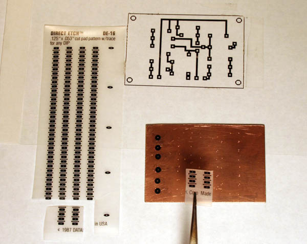
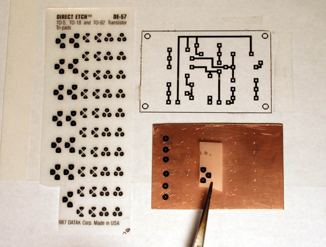
The pattern for the Tweak-O doesn't use ICs. If the circuit you are working with does, don't try to lay out the dual-in-line pin (DIP) format for a chip using donuts; dry transfer material is available that is precisely registered and can be cut for any DIP pattern length (left pic). The typical 3-lead triangular pattern for transistor leads can be defined with donuts, or dry transfers (right pic):
Once you have all of your pads for components in place, add the lines (usually called traces) that connect them. You can use either the marker or resist tape for this job. The marker is quicker for simple boards (left pic). Resist tape is usually neater and permits putting down finer lines, but installing it takes longer. Run it from pad-to-pad, hold down with the knife, and pull against the blade to cut it (right pic):
Once you have the pattern defined on copper, the board is ready to etch.
Etching The Board Using Ferric Chloride
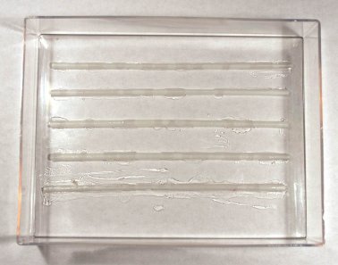
My kit comes with a plastic tray (actually half of a polystyrene box,) but any similar-sized vessel of plastic, rubber, glass or ceramic will also do. If you find a small one that already has ribs on the bottom, grab it. I could not, so I added ribs to my plastic one by slicing a few cocktail straws in half and gluing them in place with quick-setting epoxy:
The ribs make it easy to get a pair of forceps under the board to lift it out of the bath.
Most references I have seen recommend warming Ferric Chloride (usually by putting the open bottle in a bath of hot water) in order to speed the process and avoid undercutting the resist. It's a good idea, though not necessary in my experience for small boards that don't have fine lines.
Note that while Ferric Chloride is not corrosive to skin, it will badly stain both skin and fabric. Take care when pouring, and when removing the board.
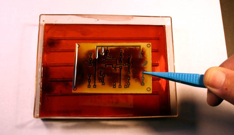
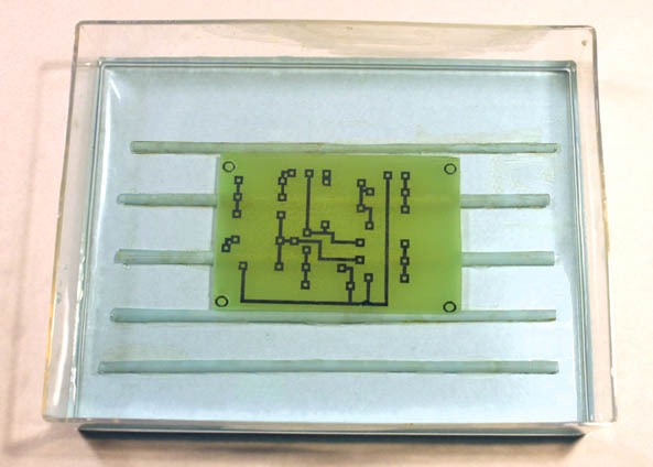
Lay the board in the tray and pour in enough Ferric Chloride to just cover it. Agitate the tank every few minutes, and lift the board out periodically to check progress of the etch:
Disposing Of Ferric Chloride
Dumping used etchant down your sink or toilet can be hazardous to your plumbing, and the copper in the solution is toxic. This reference:
http://www.diystompboxes.com/smfforum/index.php?topic=50426.40
includes notes on using baking soda to turn the solution into solid waste that can safely be thrown out with regular trash.
Etching Using Sodium Persulfate
I had never used this material before trying it for this article. The directions on the label suggest a dilution of one-half pound by weight to one gallon of water, which I translated to one-quarter ounce by weight (about a rounded teaspoon by volume) per four ounces for making a small batch. I used the hottest water I could get from my tap and stirred the powder in with a plastic spoon till it dissolved completely. One caution: When diluting Sodium Persulfate, never add water to a mass of the powder; always add the powder to the water. Doing it the wrong way can result in spattering that verges on explosive.
I used the solution exactly as I did the Ferric Chloride. Within 15 minutes, the solution started to go light blue as the copper on the board started turning to Copper Sulfate. The process took a couple of hours, much longer than Ferric Chloride, but it did ultimately work well. It's very easy to see when etching is complete:
Other references say that Persulfate solution should be warmed slightly during etching (often by placing the tank in the middle of a pan of hot water) to speed the process, and I'm going to try this next time.
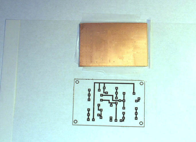
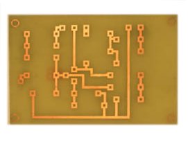
When the board is fully etched, rinse it thoroughly in running water. Then strip the resist with acetone:
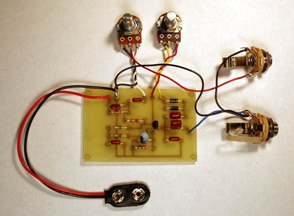
The board is ready to drill and stuff. Just to make sure that I hadn't made any mistakes, I went all the way--drilled it, stuffed, wired straight through and tested:
It works! As I noted earlier, this board can be dropped right into the Tweak-O design in Projects, should you wish to build this way.
I hope that you found this introduction useful, and that it encourages you to try making more complex PC boards. Please direct any questions or comments to smallbearelec@ix.netcom.com.