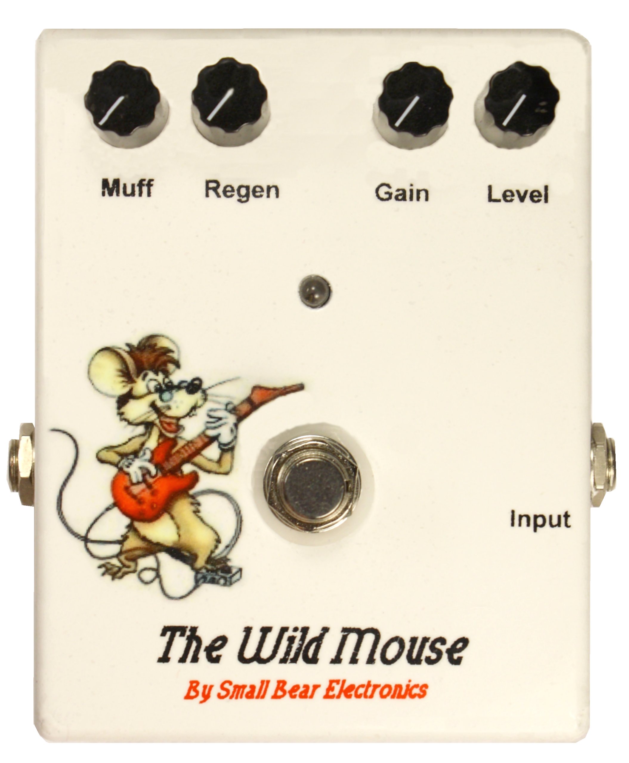
The Wild Mouse
© 2012 By Small Bear Electronics LLC
I described my first version of this pedal in Electronics Now magazine some years ago. At the time, a lot of basic stompbox components were still either unreasonably expensive or not easily available. This definitive version incorporates everything I have learned about building pedals over the last ten years, and it benefits from the many OEM parts that Small Bear has made into off-the-shelf items. The version shown in this article can be done on perfboard, but a full kit with PC board and tooled case is also available. The instruction manual for the kit is here.
I first started fiddling with the circuit back in the 70s. The Wild Mouse is a tunable active tone boost; if you like playing through a wah pedal that is "cocked" in mid-travel, the WM nails those sounds over a wide tonal range. With it, you can duplicate a number of classic licks (the Beatles' "Paperback Writer"and "Day Tripper" come to mind), and it is also excellent as an driver for a Fuzz Face or other distortion.
Here are a few sound clips. The first one is the unmodified sound (bridge pickup of my Guild Bluesbird.) The others are of the same lick with the effect on, with progressively more capacitance in the tank circuit.
There are a couple of things going on here that make the WM sound not quite like anything else. The "honk" results because you are "ringing" a resonant circuit. The lower the resonant frequency of the tank, the deeper the muff. Some distortion comes from overdriving the op-amp inputs. The Gain pot controls the distortion level, and the Regen pot adds controllable feedback for edginess. While the original WM incorporated trimpots that I set to clamp the gain into a "normal" range, the circuit can easily be driven into some insane oscillation. I don't particularly like this kind of over-the-top weirdness, but some people clearly do, so I purposely made the trimpots in the original into panel controls with a wide sweep.
How It Works
Here's the schematic:
The two stages of IC1 are connected as regular inverting amplifiers, but with positive feedback at a level set by R9. R7 sets the gain of the first stage, and the tank circuit formed by L1 and capacitors C3-C4 add the funky resonant peak to the output taken from IC1-a. Earlier versions of the WM used separate capacitors and a rotary switch. You can still go this route if you wish. However, I found that a parallel capacitor that is allowed more or less in-circuit by potentiometer R3 gives more control possibilities. A continuous pot can be used if you want to tweak, or you can use a pot with detents for presets. Yes, you can also sub a digital pot and control it with a Molten Voltage chip.
S2 is a standard DPDT alternate-action stomp switch. It provides true bypass with control of the in-use indicator LED using a variant of what is commonly called the "RAT bypass" circuit. When S3 is in bypass mode, level control R15 grounds the base of Q1, a darlington transistor, and so cuts it off.
The number of components and the tooling requirements make the Wild Mouse an intermediate-level project. Before trying this one, you should have built at least one pedal that required tooling of a metal case and working with perfboard or Veroboard.
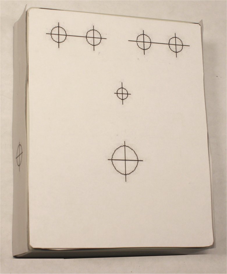
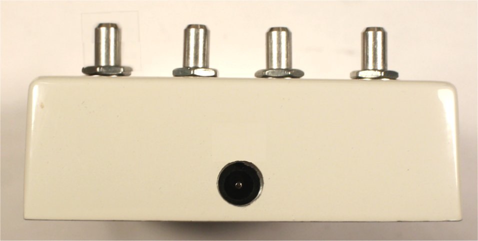
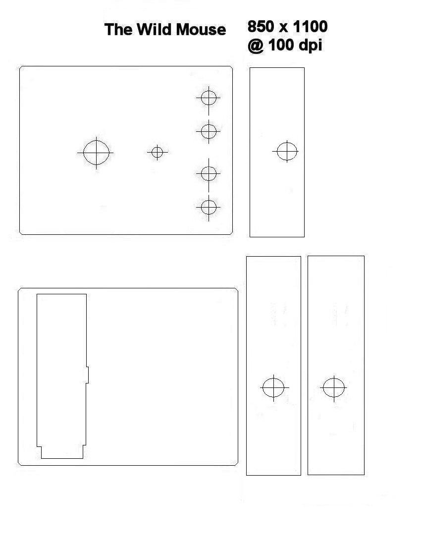
Begin by printing this set of drilling templates for the enclosure. Cut the individual pieces to size with a sharp scissor, and tape in place as shown using double-sided tape.
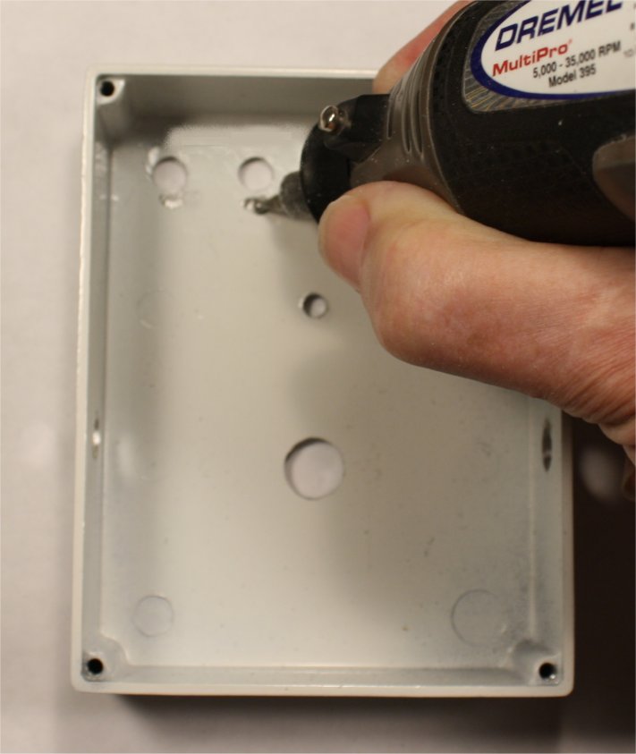
Drill the holes now. I use a step drill (common trade name Unibit), but ordinary twist drills are also fine.
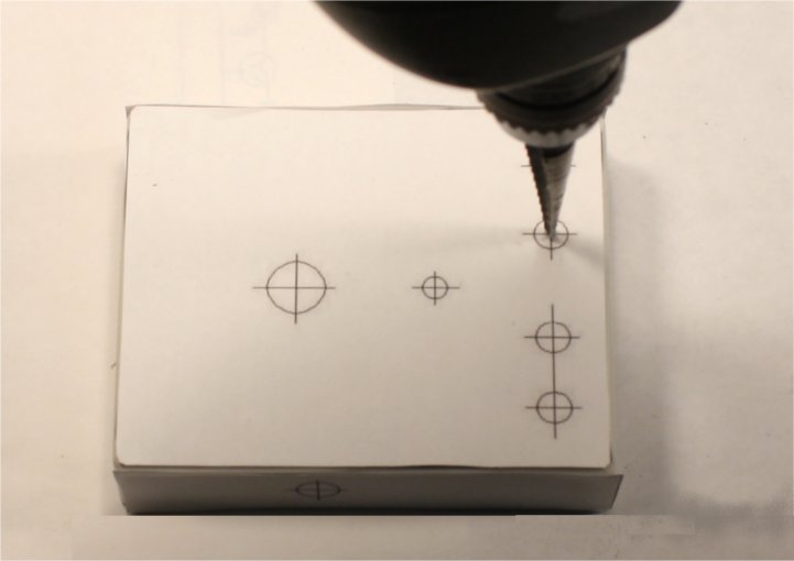
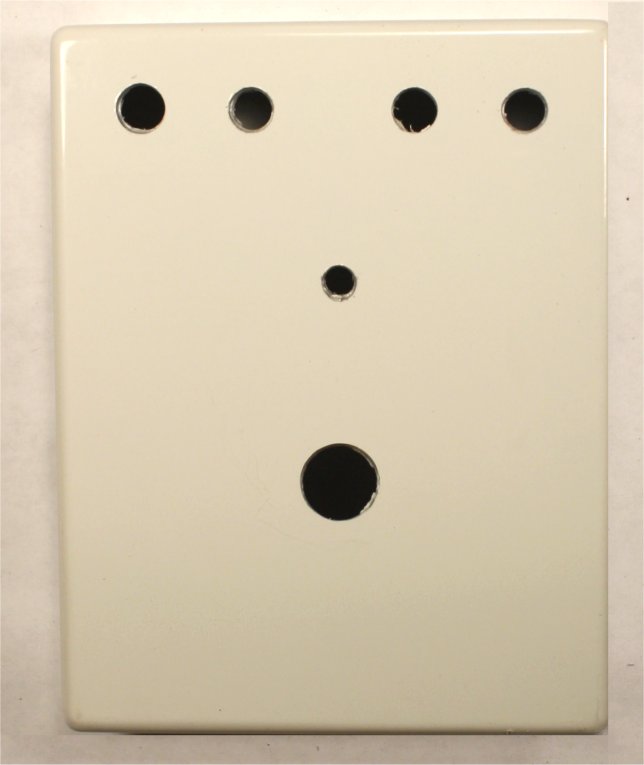
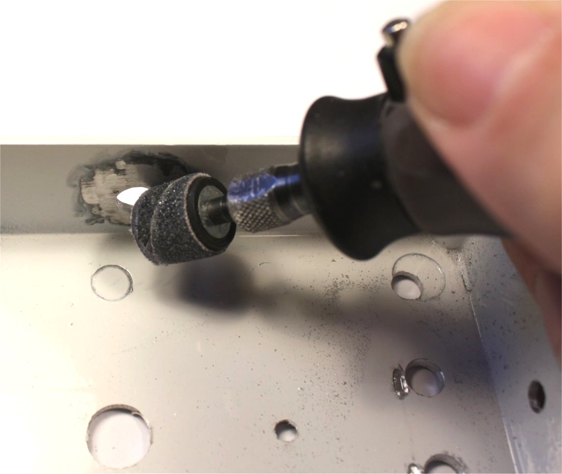
Note: The enclosure shown here is a pre-powder-coated white. If you start with an unpainted box, don't do any painting or decorating yet. If you are working with a pre-coated box, make sure that you grind or sand away the color around the holes for the input and output jacks.
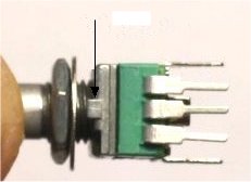
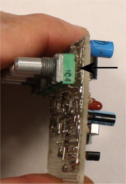
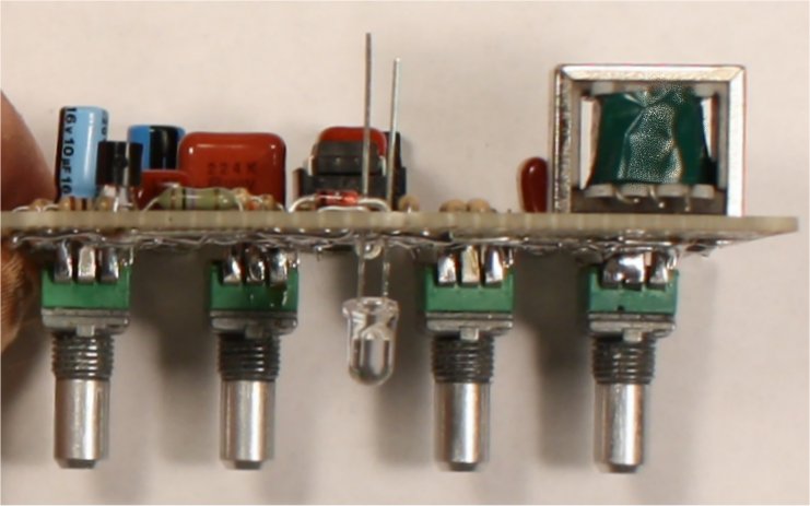
The pots that I chose for this build have anti-rotation tabs, and I decided to use them. This requires grinding a narrow, shallow slot below the hole for the pot as shown in the right-hand pic.
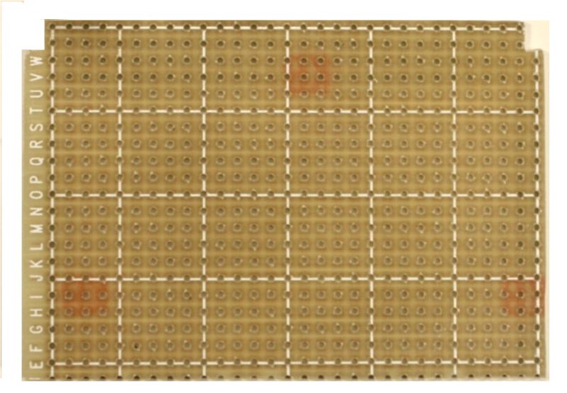
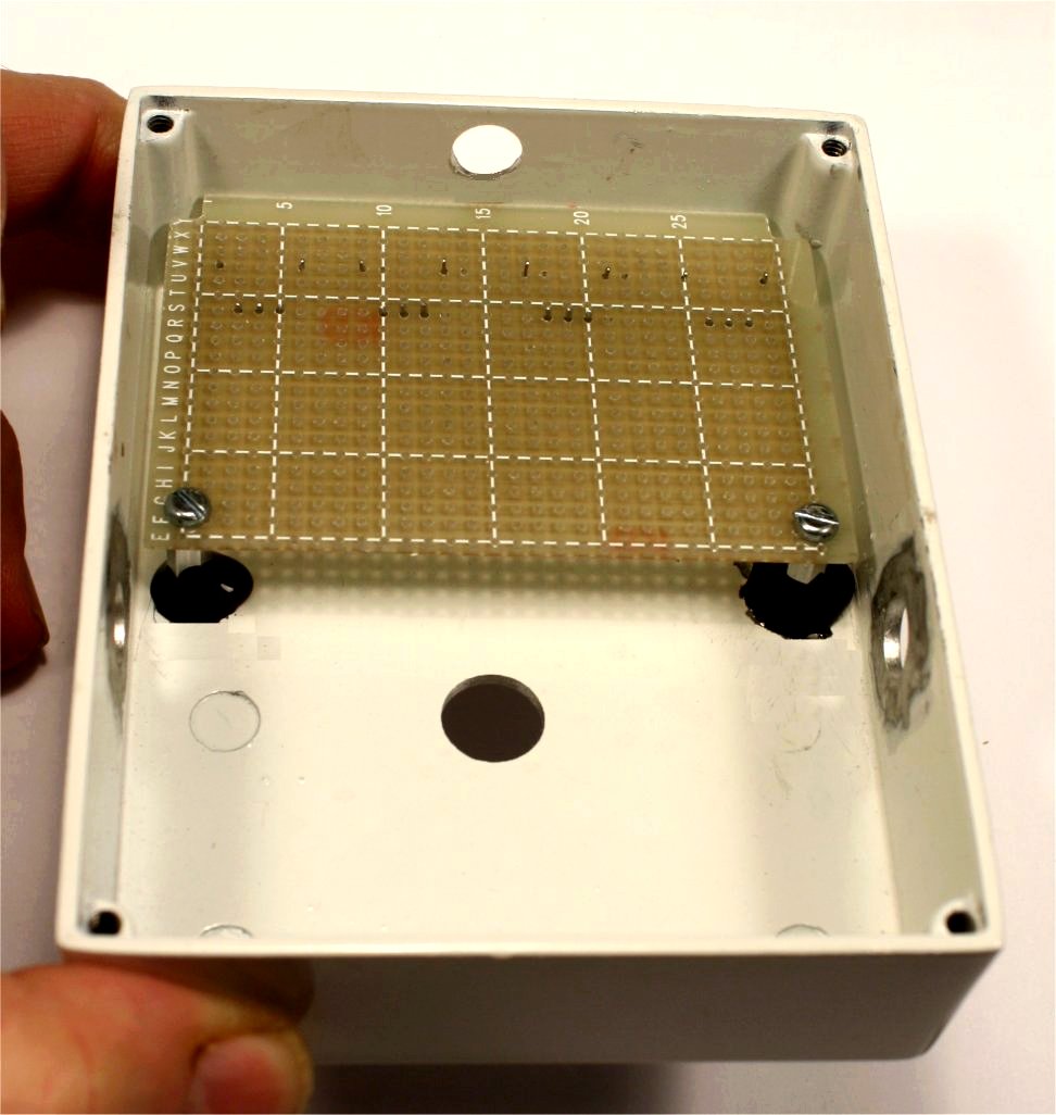
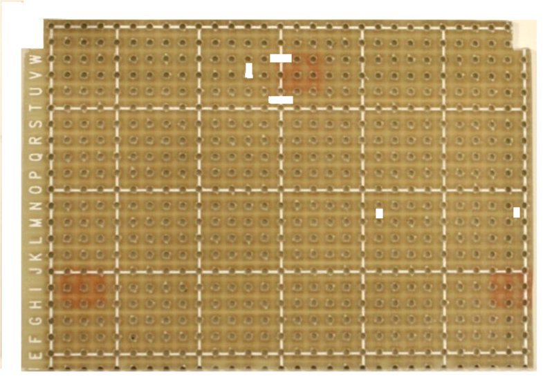
The next step is to tool the blank perfboard, create cutouts for the posts of the enclosure and establish the locations for two mounting studs. I started with one of my large pad-per-hole boards, but any similar material will do.
Use any combination you want of cutting, scoring or grinding to create the corner cutouts. (IMORTANT NOTE: Machining epoxy-glass circuit board creates fiberglass dust, which is noxious stuff! When doing any tooling of the board, wear disposable gloves and a face mask!) The picture shows what you want to wind up with.
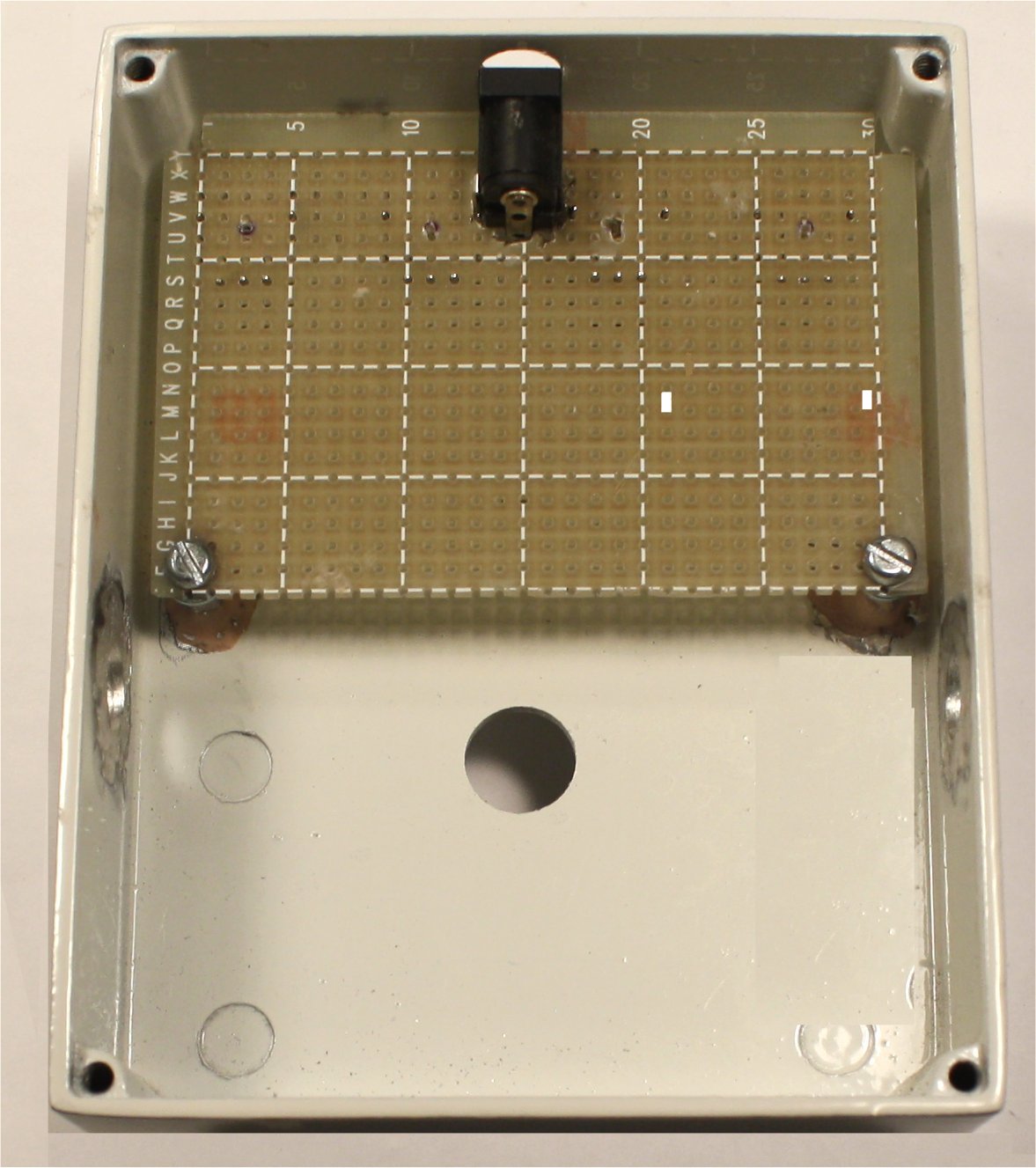
After you have done the cuts, bore two 1/8" holes at the lower left and right corners for mounting studs. Carefully lay the perfboard in place on the floor of the enclosure, and mark the points defined by the mounting holes. Remove the board and sand clean around these points to make them ready as locations for mounting studs.
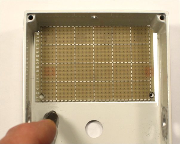
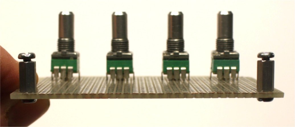
Temporarily mount the pots and install screws and 3/8" studs in the mounting holes of the board. I found that by adding a 4-40 screw in the bottom of each stud as shown in the left pic, I could shim the board to exactly the right height with these pots. Set the assembly in place in the enclosure. It should go in fairly easily and without binding. If your drilling was not accurate, this is where it will show up. If your registration is only a little off, you can sometimes recover by filing holes larger.
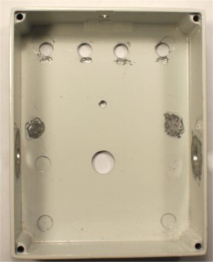
Once the board and the pots drop in, clean up the studs and their mounting areas with acetone. Glue the studs in place and reinforce with more epoxy in the usual way.
The last step in tooling the board is to route slots for the terminals of the DC power jack. and the transformer mounting tabs. I usually do this with a fine (#63) drill. Mock-up the assembly once again, and be sure that the registration of the power jack is correct with respect to its hole in the enclosure.
Now disassemble and paint if you need to, or just do your decals. The shell is finished, and you are ready to stuff and wire the board. Here's the layout, and a parts list:
Some suggestions and notes:
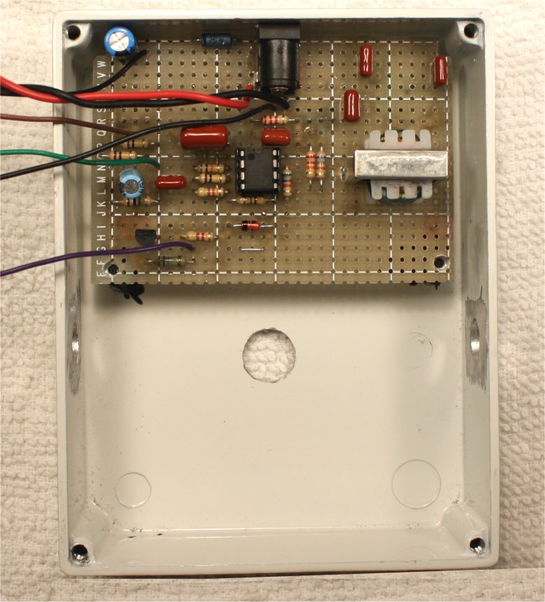
R12 should be a minimum of 100 meg to avoid switch pop. I got this by putting five 22 meg resistors in series, though 100 meg resistors are sometimes available as surplus. I installed them radially, soldering the bottoms in place first, and only later connected them when doing the wiring.
L1 can be a wah inductor, but the primary of a common audio transformer has about the right inductance, works nicely and is very cheap. The original WM used the Radio Shack p/n 273-1380, and I believe that's still available in RS stores. The redesign uses Mouser p/n 42TM013, and it is available on my Stock List.
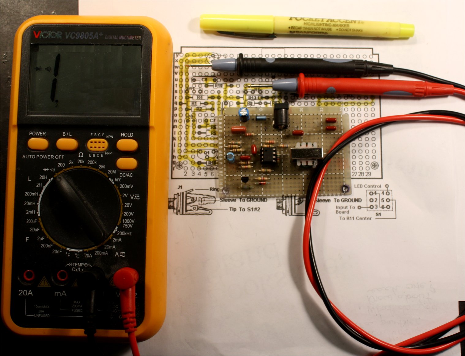
To help ensure that a build works the first time I power it up, I use a yellow highlighter to mark a connection on the layout drawing as I make it, and then test the connection for continuity:
I suggest mounting all of the components except the LED and the pots and doing all the bottom-side wiring before those last items are soldered in place. When installing Level pot R11, clip off the supporting tab nearest the edge of the board so that it does not short to the wiring below. The tab of Muff pot R3 that is closest to capacitor C3 needs the same treatment. The LED inserts from the solder side with its negative side (short lead) in J14.
At this writing, I don't have the 9mm right-angle style pots in 100K reverse audio, so I did this build with the regular version and soldered leads to the pins. 100K audio is available if you are building now and want all the pots mechanically identical, but the direction of control is reversed. 100K reverse audio will be available in autumn, 2012.
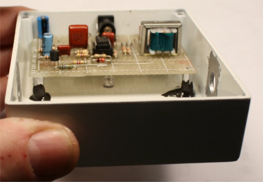
To fix the height of the LED, set the board in place and let the LED fall all the way into its hole. Then back it out to the height you want and bend its leads flat to the board. Solder in place on the solder side and clip the remaining leads on top.
Lift the board out and refer to the layout drawing to add the leads that go to the jacks and the stomp switch. Once this is done, the board can be screwed down in the case and is ready for final wiring. At this stage, I usually rest the front of the case on a towel to avoid accidentally damaging the finish.
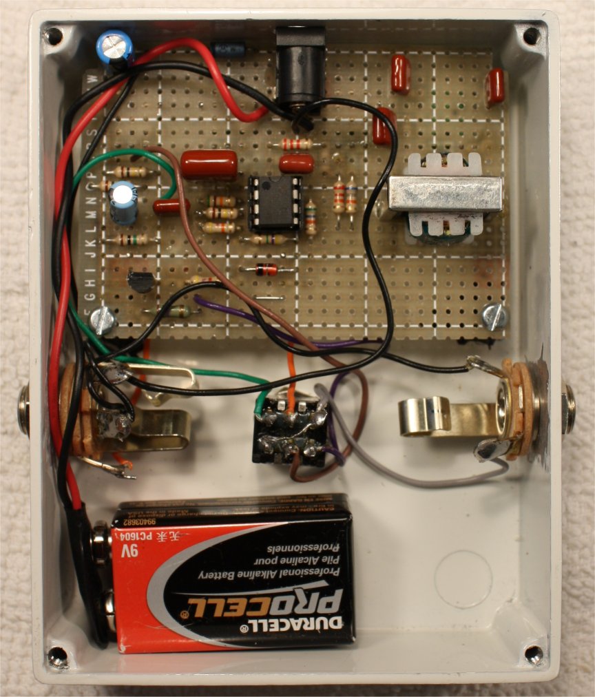
Install the stomp switch and jacks and refer to the layout drawing for the final wiring.
Setup and Testing
Connect a battery or power supply and plug your instrument into J1. Start with the Regen, Gain and Muff controls almost fully counterclockwise and the Level control about half-way up. You should see activity from the in-use LED and the boost should be clearly there. If it doesn't kick in after you click the stomp switch, there's an error somewhere; see the troubleshooting tips. If you hear a clear, undistorted treble boost, CONGRATULATIONS!
Using It
With the initial settings, as I noted, you have a useful treble boost. Now run the Muff pot through its travel and you should hear progressively more "throaty" tonalities added to whatever you are playing. Try various settings and vary the Regen and Gain pots at each Muff setting to get an idea of how they interact and what tones you might find useful; I find that Regen and Gain have a more pronounced effect at low-frequency settings of the Muff pot--YMMV.
Troubleshooting
If you get no sound at all, first make sure that the chip is getting powered (about 8.75 volts at pin 8). Also make sure that Vref is about half the supply voltage, and that it is getting to the points where it is supposed to be. If the power is OK, use your amp as an audio probe to see if maybe you have made mistake in the wiring to the external components. If you are still stuck, go back to the technique of testing each joint and trace and marking off connections--it works! I built the model you see here from the posted drawings and I am confident that they are correct. However, if you do come across an error, please let me know so that I can help other builders.
Mods and Substitutions
Obviously, the values of C3 and C4, the capacitors in the tank circuit can be varied to taste. Beyond that, some people will want to be able to control the "wildness" or frequency range externally. I chose to leave my prototype as you see it, but I have done a few experiments and will suggest a route to pursue.
Since the Muff pot is ground-referenced, you can easily bypass it in favor of an external resistance. The jack shown would be a Switchcraft #12A or similar. Any passive swell pedal with a 100K to 200K resistance can plug in here. The result is very like a distorted wah.
If you put the LDR-side of a high-resistance photocoupler in parallel with the Muff pot, it will be essentially out of the circuit unless power is applied to its associated LED. You can the vary the frequency by driving the LED directly from an external control voltage. With different settings of the Regan and Gain controls, you can get modulations ranging from a light vibrato to really gnarly phasing. I used a Silonex NSL-32 in my tests, so other similar devices can be expected to work.
I have not had time to try an envelope generator for driving the filter, but I am sure that would also be interesting.
I hope that you enjoyed building the Wild Mouse, and that it becomes part of your regular lineup of effects. Please direct comments and questions to smallbearelec@ix.netcom.com.