Anyone who has ever tried to power a piece of high-gain audio gear with an ordinary department-store "wall-wart" knows that the results are usually awful. Because wall-warts are designed to be sold as cheaply as possible, they contain only the barest minimum of filtering. The ripple current that gets through shows up in an audio output as hum--unpleasant at best, and often intolerable. The solution for powering stompboxes and other portable audio devices is a power supply that is well-filtered and tightly regulated--a Small-Wart.
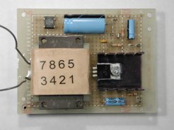
The Small-Wart 200 incorporates a flat-pack transformer that can deliver over 200 ma.--easily enough to power a board full of pedals. It is small, very physically rugged, and has a detachable AC power cable for easy storage in a gig bag. Its output is physically isolated from the chassis, so different grounding requirements can be accommodated easily. A "semi-fixed" trimpot, adjustable from outside the case, sets the voltage level.
Because it is powered from the AC line, the Small-Wart 200 is not suitable as a first project for a complete novice. In particular, making correctly the connections to the primary of the transformer and insulating them carefully takes some skill. You should also have some experience with tooling and painting a metal case. If you have built a couple of simpler projects successfully and now want a line-operated power supply for them, a Small-Wart may be the ticket.
International Customers Please Note: The build shown here is strictly for use with 110 volt power. While it is possible to wire the power transformer for 220 volts, I can't give you construction information or supply the parts needed for such builds. The kit in the Stock List is Not appropriate for 220 volt environments.
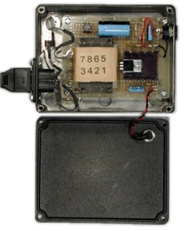
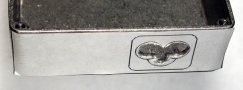
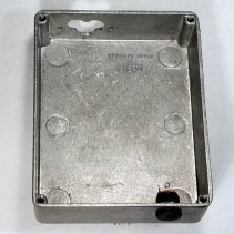
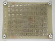
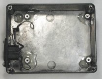
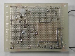
The enclosure shown is a Taiwanese clone of the Hammond 1590-BB, but you can also use either the Hammond or the similarly-sized Eddystone equivalent. The perfboard that holds all of the circuitry is mounted on aluminum standoffs that are secured with epoxy cement. The resulting assembly will take considerable abuse if it's built carefully.
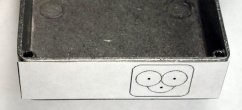
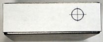
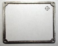
The first step in preparing the case is creating the clover-shaped hole for the 3-wire AC inlet. This must be cut accurately, both for safety and esthetics, so I have specified a particular part for the inlet and created an actual-size drilling template. You can download Figure 2 from here. Cut out the template, and tape it carefully to one end of the box. The right-hand edge of the rounded rectangle surrounding the inlet should be 9/16" in from the edge of the case. Drill two 3/8" starter holes. I used a Unibit, but ordinary twist drills and/or a reamer are also fine. Drill the third pilot hole to 3/16". Don't be tempted to make this one larger; you can lose control of the drill when it punches through! Cut or file out the center section.
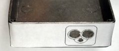
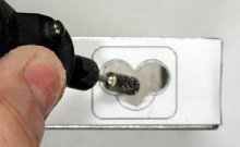
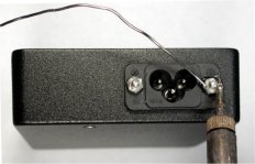
How you proceed from here depends on the tools you have. It is possible to do the rest of the cutting by hand with round files, but a rotary tool does it much more efficiently. You can use a Dremel high-speed cutter, or the tool shown here is a EuroTool "inside-ring" burr #BUR970.00. The power inlet should fit snugly into the cutout, and you can then locate and drill the two holes for the screws that secure it.
 >
>
The Output Jack(s)
You have choices about: how many jacks you include; what types, and where they are located. The standard "BOSS-style" plastic jack is definitely the easiest to work with, and Figure 9 download from here is an actual-size drilling template for mounting one of these on the end panel opposite the AC inlet. In the same general way that you did the pilot holes for the AC inlet, tape this drilling template to the end panel and drill the hole.
Some people just don't like the appearance of those plastic jacks. It's possible to use the ones that have a metal bushing, but for many applications you want the bushing insulated from the case. If you want to use metal power jacks, the article on the Small Wart 60 shows the techniques I used to create a "platform" for mounting them using fiberglass auto-body filler.
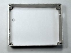
Once the holes for the power jacks are done to your liking, locate and drill the hole for the on-off switch. I have specified a particular toggle switch that has a short lever and a compact body. Other parts will surely work, but be sure that any substitute you buy will fit mechanically. Figure 12 download from here is an actual-size drilling template that fits in the bottom of the case. Use a center punch or scratch awl to mark the center of the 3/16" hole, and drill it. Make sure that the switch fits the hole snugly.
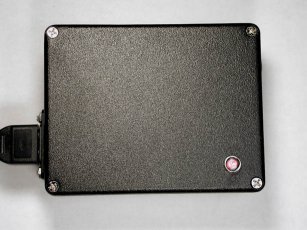
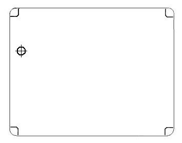
Most people will want a pilot LED to indicate when the Small-Wart is on, so you should drill the hole for whatever bezel or LED holder you want to use. I located this on the lower right of the screw-on lid. The chrome bezel shown (and included with the kit) requires a 1/4" hole. Here's a drilling template.
At this point, with all hardware removed, the case can be painted. I usually do it by sanding and cleaning up with solvent, applying a primer and then a couple of coats of spray enamel, and baking for an hour at 150 degrees in a small toaster oven that I keep for the purpose. Finish with an automotive clear coat. You can find detailed "recipes" for finishing metal in many on-line DIY references.
Start To Put It Together
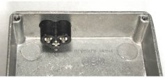
The AC inlet goes in first. This fixture must be held rock-solidly in place and not have any "play" that would permit it to work its way loose when the power cord is inserted or removed. If you have a riveting tool, this is a good application for it. I didn't, so I created the equivalent of rivets by using solder to lock the threads of the two 4-40 mounting screws. Sand or grind at the point where the solder lug will rest so that it makes good contact with the case. Assemble with the solder lug under the screw next to the power switch. I have a 35-watt iron, and I heated each screw thoroughly with it before applying solder and letting it melt into the crevices between the threads. Figure 16 shows the soldering process. When I was done, I used a cutoff wheel on my Dremel tool to shorten the screw ends and an abrasive stone to remove sharp edges. WEAR GOGGLES FOR THIS! THE PIECES CAN AND DO FLY LIKE BULLETS! Make the solder connection between the solder lug and the ground pin of the AC inlet. Carefully fasten a rubber foot at each corner of the bottom of the case. Solder short connecting leads to the switch, insulate them with 3/32" heat shrink, and install the switch. Make the connection from the center switch terminal to the power inlet and set up leads on the outer switch terminal and the power inlet for later connection to the transformer.
Building The Circuit Board
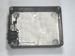
First, mark the locations for the mounting studs with a scribe as shown in Figure 18. The studs are secured to the bottom of the box with epoxy cement. To get good adhesion, I prepared the locations where the studs mount by sanding lightly and cleaning up with solvent. Then I screwed the studs to the board (Figure 19). I cleaned the bottoms with sandpaper and solvent, applied a drop of epoxy cement to the bottom of each one and gently set the assembly in place. When the adhesive had cured, I was able to remove the screws and reinforce the studs with more epoxy. The result looked like Figure 20.
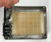
To precisely locate the hole for the knob of trimpot R1, screw the board in place. Then bore a hole right through the case with a #59 drill at index V23 as shown in the board layout drawing and Figure 21 below. Drill this hole as straight and true as you can. Remove the board and enlarge the hole in the case to 1/4 inch diameter. If you want, you can stick the trimpot in place temporarily on the bottom of the board and see how it will fit and feel later when the board is wired.
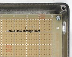
Figure 22 shows the board layout in X-Ray view. I suggest that you stick with this arrangement, because it puts the input and output where they need to be and gets all the components connected without jumpering.
Before you begin to insert components and wire, note that the transformer pins don't fit exactly on the .100" centers of the perfboard; you will need to bore a hole with a #59 drill between index B10 and B11, and another between R10 and R11 in order to accommodate it. It also helps to enlarge slightly the other mounting holes: B3, B7, B14, and the corresponding holes in row R. Bore the 1/8" hole for the screw that secures the voltage regulator at index J23.
Figure 23 and Figure 24 show the top and bottom of the board. When you wire point-to point in this way on pad-per-hole, you do not usually wrap connecting wires around components; it wastes space and can cause shorts. Butt a connecting lead against the point to which you are soldering, hold it in place with locking tweezers or some other "third hand" and then solder. An exception to this rule is the wiring to the transformer pins. I used insulated leads for the power input, wrapped them around the pins before soldering, and tacked them down with epoxy glue to make sure they can't wander.
Insulating the regulator from the heat sink is not necessary, but do use silicone grease when you mount the LM317; it can get a little warm, and it needs help getting rid of heat. Also, use a compression lockwasher (provided in the kit) under the mounting screw. When done, the board is screwed down in the box and is ready for testing and final wiring.
Testing
With the transformer primary leads temporarily connected (and covered up!), I connected a voltmeter between the +7.5 to 9 volt pin and ground. Then I plugged in the line cord and applied power. Rotating R1 gave me the proper voltage range. I also made sure that I got illumination from an LED connected from the LED contact to ground. In my prototype, current-limiting resistor R4 is 10K. The kit includes a high-brightness red LED that is brightly lit even with that much series resistance. Ordinary LEDs can be used, but R4 will need to be lowered appropriately.
To test the regulation and current limiting, I used a 50 0hm power resistor and a 500 ohm 2 watt control that I had in my junk box. Connected in parallel, these gave me a good variable load. With no load connected, I set the output of the Small Wart to exactly 9 volts. I connected the load and a meter set to 400 ma. across the output. At a draw of 200 ma., the voltage was still 8.85, so clearly the regulation is good! Then I started to very slowly lower the resistance. The currect limiting began to kick in at about 260 ma. output, and within 15 seconds the current had gone down to 23 ma. This shows that the resettable fuse X1 is working: When the current through it passes its "trip" value, it goes into a very high resistance state. I removed the load and turned off the Small Wart momentarily. When I turned it back on, it went back to normal operation. I made the connections to the transformer primary permanent and insulated them.
Wiring The Output(s)
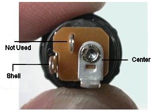
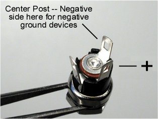
This will vary some with your application. The standard "BOSS-style" output jack has three contacts, because it includes a normally-closed switch. When it is used in a battery-powered device, the switch disconnects the battery when a power plug is inserted. We are using the jack as an unswitched output, so only two contacts are used (Figure 25 and 26). For most applications, the center contact will be the common negative.
Patch Cords
You will want to have a few of these available, usually about 3 feet long. The plug in the parts list has a 2.1 mm inside diameter, and it mates correctly with the "BOSS-style" output jack. Depending on what you are powering, you may need a different type of plug on the equipment side. Since I use 2.1 mm power jacks on all my gear, I use the specified plugs and wire them shell-to-shell and center-to-center. The cable is a #22 zip cord that is commonly sold for connecting miniature speakers. Some brands ID the conductors with a stripe on one of the leads, while others have one tinned lead and one bare copper. Musicians will want to ID the plug barrels for easy tracing in stage environments, and this can be arranged either with colored heat shrink tubing or a liquid plastic/rubber coating such as is used to put handles on metal tools. See the article on the Small Wart 60 for some examples.