© 2010 by Small Bear Electronics LLC
Anyone who has tried to power a piece of high-gain audio gear with an ordinary department-store "wall-wart" knows that the results are usually awful. Because wall-warts are designed to be sold as cheaply as possible, they contain only the barest minimum of filtering. The ripple current that gets through shows up in an audio output as hum--unpleasant at best, and often intolerable. The solution for powering stompboxes and other portable audio devices is a power supply that is well-filtered and tightly regulated: a Small-Wart.
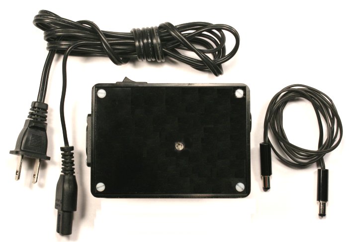
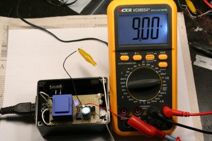
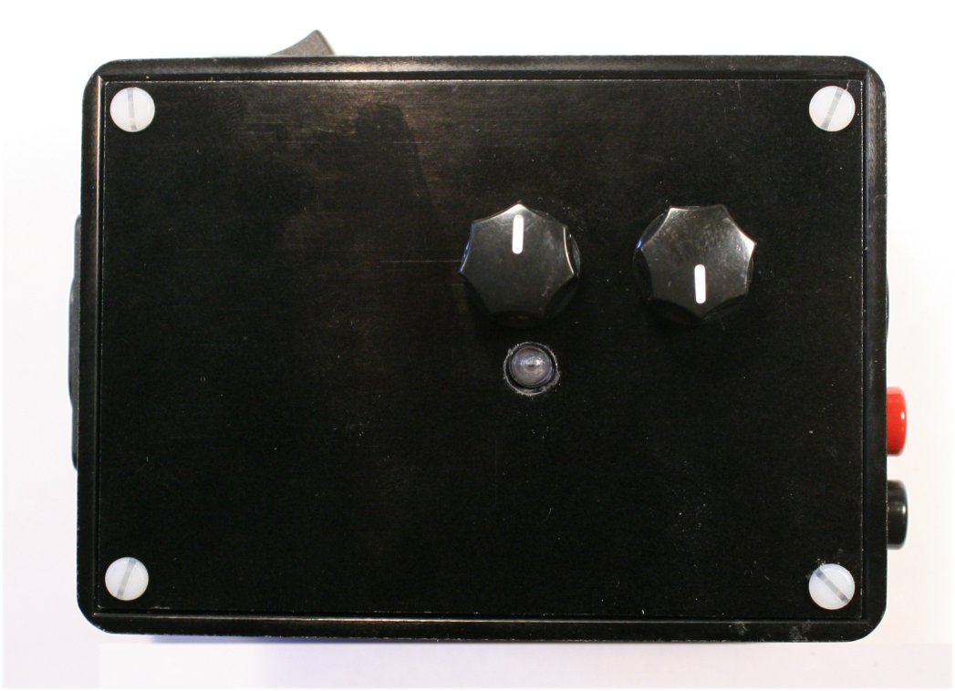
The Small Wart 125 can supply up to 125 ma., so one unit will easily power several ordinary pedals. It is relatively easy to build and not much more expensive in parts than the wall-warts that it eliminates, so building several to have in your gig bag is feasible. Other useful features are an on-off switch, a detachable AC power cable, a resettable fuse for short-circuit protection and an in-use LED. It's a great building block for dealing with DC power issues in a gigging environment, like ground loops and mixes of positive- and negative-ground pedals. Within the basic design, many configurations can be accommodated to support your needs. This article will show a "basic" fixed 9-volt, and a "deluxe" version with variable 7.7 to 9.2 volt output, dying battery sim and meter test points.
Because it is powered from the AC line, the Small-Wart is not suitable as a first project for a complete novice. In particular, making correctly the connections to the primary of the transformer and insulating them takes some skill and a lot of care. If you have built a couple of simpler projects successfully and now want a line-operated power supply for them, a Small-Wart may be the ticket.
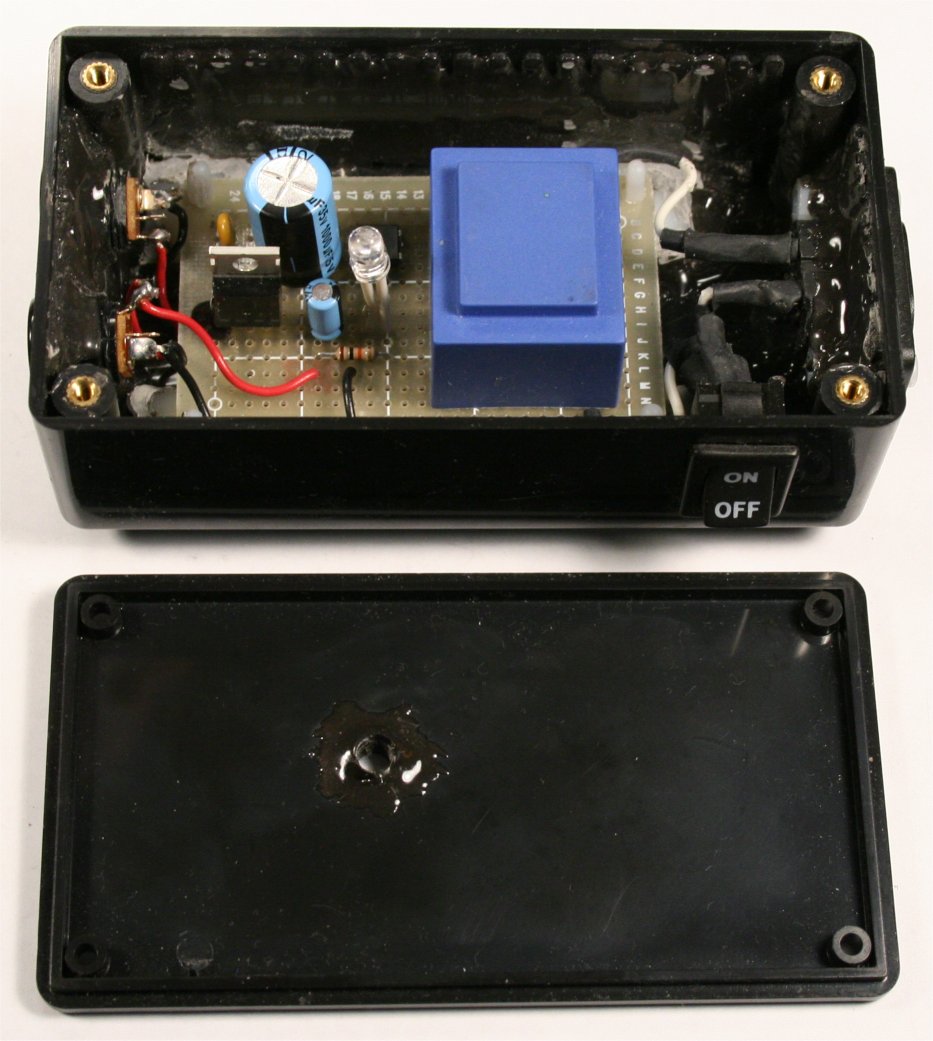
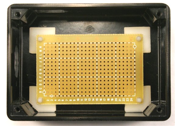
I tried two different plastic enclosures in prototyping this puppy. The build on the left is in a Hammond model 1591C. The ribbed sides of this enclosure make it strong, but they make tooling more difficult than I was happy with; I had to fill in the areas between slots with epoxy cement in order to have a flat purchase for the fittings. I mention it because it is commonly available, and it is workable for the purpose. If you happen to have one (or something like it,) you should be able to adapt it for this build. The metal corner studs in the 1591C are not a problem because the construction of the lid shields them completely from the internal workings.
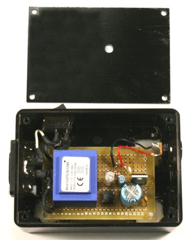
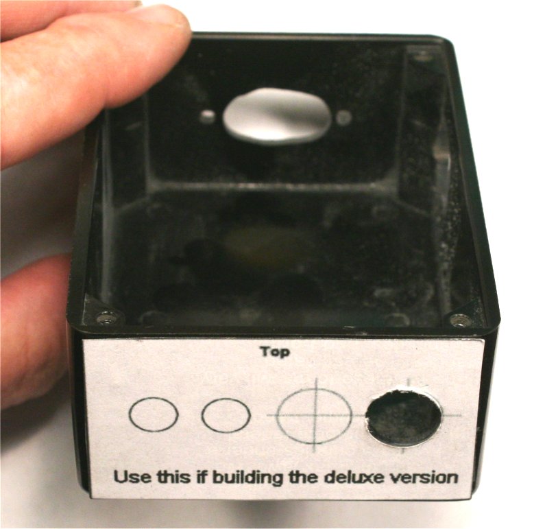
The right hand pic shows the enclosure I ultimately chose for this article and for the kit. It's phenolic, measures 4" x 2 7/8" x 1 1/2", SKU 0306N on my Stock List. It's heavy and rugged and will stand some abuse while still being fairly easy to tool. It has no metal hardware--not even the posts for the nylon screws that secure the cover. This makes it easy to implement a two-wire AC line interface, which is more convenient to work with in many situations. However, to avoid any possible shock hazard, you MUST NOT have ANY metal parts penetrating the case; the exposed parts of the power switch, LED bezel and power jack(s), and any screws/nuts that retain them, MUST be plastic. The kit includes the case and appropriate components and hardware.
Building The Basic Version
I have done my best to reduce the tooling requirements and the number of assembly steps. A PC board is in the works.
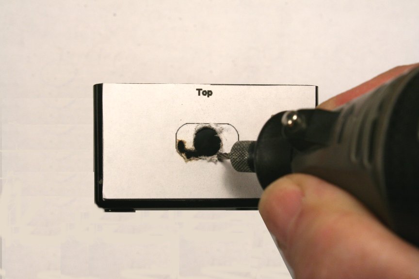
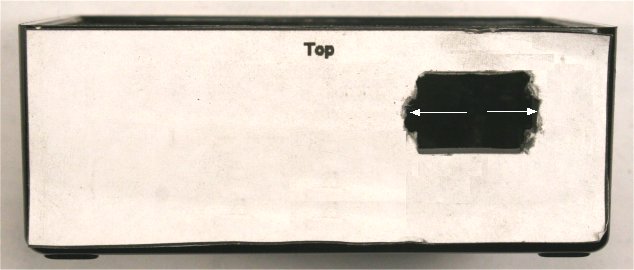
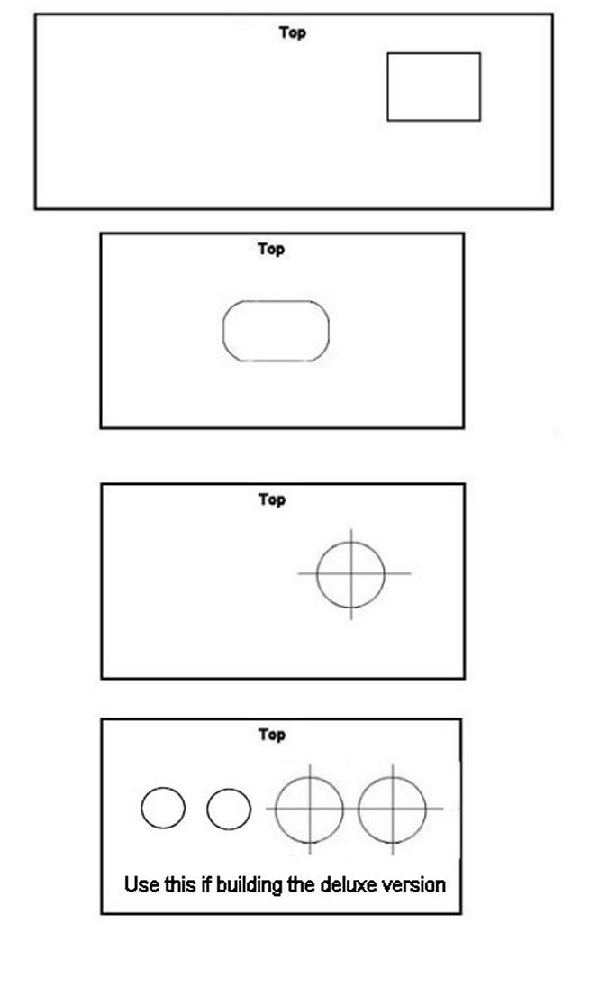
Begin by downloading the drilling templates. Cut out the template for the AC line inlet, and tape it carefully to one end of the box. Using a Unibit or ordinary twist drills and a reamer, create a 3/8" starter hole roughly in the center. Work slowly and carefully to avoid cracking the case. Enlarge and widen the hole to its oval shape using a round file, or, preferably, a Dremel or similar rotary tool with a cutting burr. The AC inlet must be mounted securely for safety reasons, so sloppiness can't be tolerated here. If you don't have the right tools, borrow or buy them!
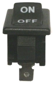
Attach the template for the power switch on the side panel and make this cutout in a similar way. This rocker switch has flanges on each end that allow it to snap in place in a precisely cut hole. Don't remove these! Rather, when you have made the rectangular cutout just large enough for the switch to begin to enter, file or grind notches as shown to accommodate the flanges.
Attach the drilling template for the DC power jack and drill this 1/2" hole. Set the AC inlet in place, and use a pick or scribe to mark the positions for its mounting holes. Drill these with a 7/64"" twist drill.
This part of the tooling is done. Give the whole surface a thorough wipe with alcohol, and you can mount and secure the fittings to the case.
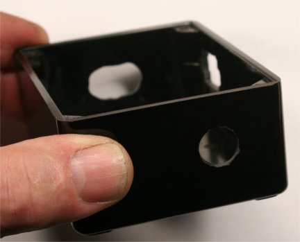
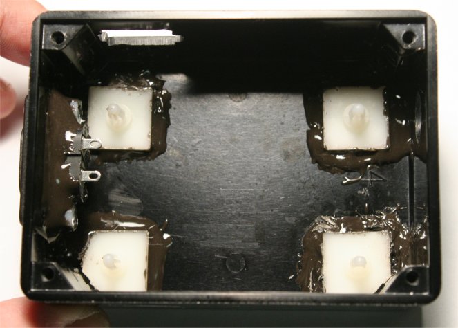
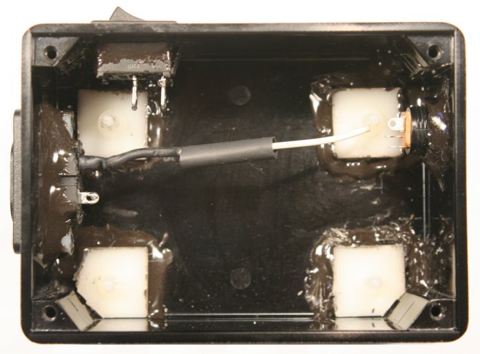
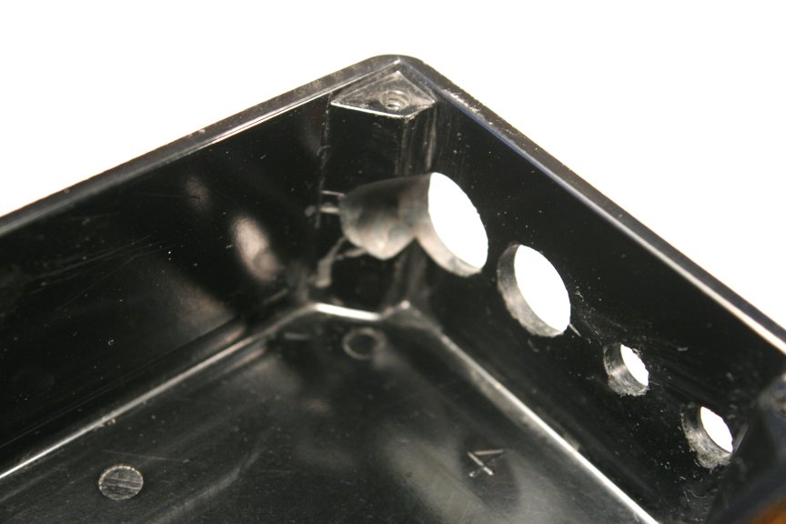
Start by setting the positions of the adhesive standoffs. Insert a standoff part-way into one corner of the circuit board, but don't let the board lock in place yet. If that happens, squeeze the "lock" of the standoff so that you can lift the board free. Slice off one corner of the standoff; this can be done by "nibbling" with a side-cutter or with a cutoff wheel on a Dremel tool. If you use the Dremel, WEAR GOGGLES!
Insert another standoff on the opposite side and slice off the corner of that one as well. Inset two more standoffs and set the assembly down in the enclosure. If everything looks like the right-hand pic, remove the adhesive backing on the standoffs and carefully set the assembly in place.
Lift the board off the standoffs for now. Mount the AC inlet with 4-40 threaded studs and nylon screws. I tried nuts for this and wasn't happy; they don't have enough threads to properly grip the screws. I repeat: NO METAL HARDWARE!
All of the fittings are secured using J-B Weld or similar epoxy cement/filler. Suggestions:
Stuffing The Board
Here is the schematic:
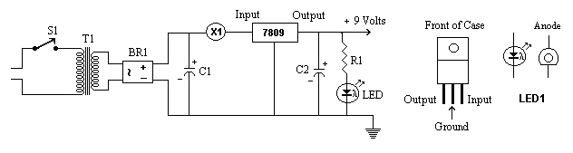
X1 is a resttable fuse. DON'T LEAVE THIS OUT. It prevents the transformer from overheating in the event of a short circuit on the output.
Here is the layout in X-Ray view:
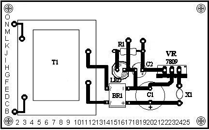
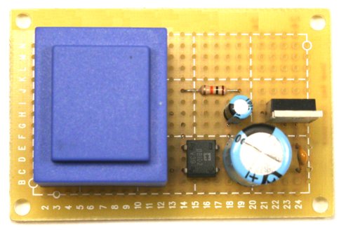
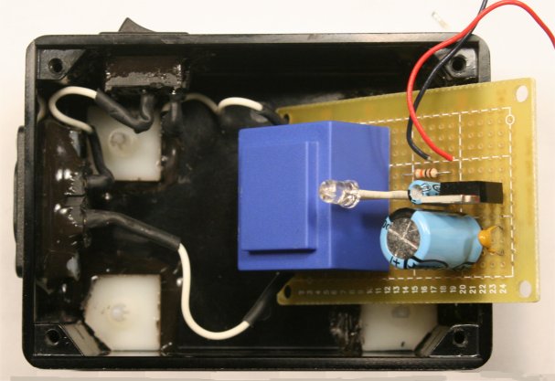
and below is a closeup of the stuffed board. Don't mount the LED yet. Mount the other components one-at-a-time, solder in place and trim leads. Then do the point-to-point wiring.
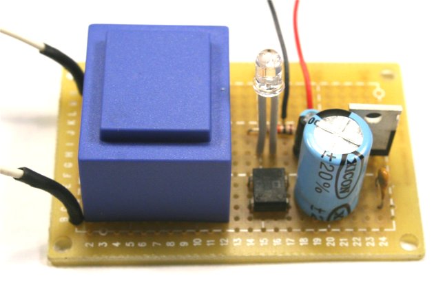
When all of this is done, cut two pieces of spaghetti tubing about 7/8" long and slide them on to the leads of the LED. Cut the longer lead down so that both leads are the same length. Insert the LED at indexes H15 and H16 with the flatted side facing C2. Solder in place.

Okay, four leads to go off-board--red for +, black for -, and two heavier leads for the transformer primary. Add a couple of short pieces of heat shrink to the primary leads and conform with the edge of your soldering iron.
Do a preliminary test:
If you have the Small Wart working to this point, you are ready to wire the transformer primary circuit. It is best to do this before final installation of the circuit board.
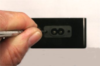
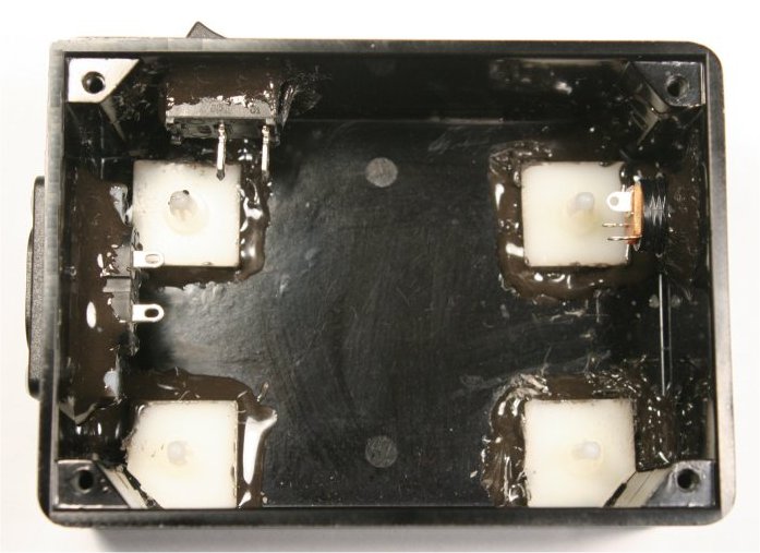
Unsolder the temporary connections to the AC inlet and clean up the contacts. Solder a short lead to the lug of the AC inlet closest to the switch (pic below,) insulate with heat shrink and use the edge of the soldering iron to conform the tubing to the lug. Add another short piece of heat shrink over this lead, solder the connection to the switch, slip the heat shrink over the lug and conform.
When all done, route the finished connection away from where the board will sit.
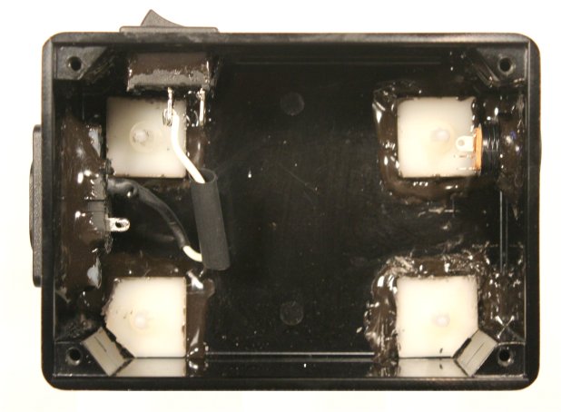
Add a short piece of heat shrink over each transformer lead. Solder the lead closest to the switch to the switch lug. Cover with the heat shrink and conform to the lug. Do the same with the lead to the AC inlet.
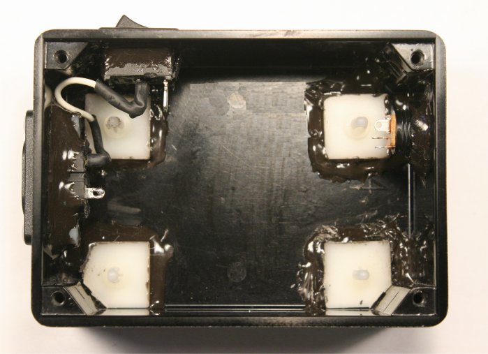
When done, you can mount the circuit board on its standoffs and press it in place. Route the primary leads away from the transformer. Solder the output leads to the DC jack. I added a drop of clear epoxy over the points where the output leads enter the board, just to make sure they stay in place. I also added a bead at the edge of the regulator IC, again for mechanical stability.
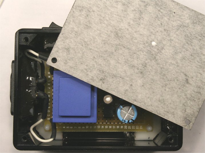
To locate the hole for the in-use LED, make sure that the LED is standing absolutely straight up. Apply a dab of White-Out on top of the component. Hold the cover over the enclosure and lower it slowly so that it just touches the LED, doing your best to keep it square with the corner posts. This will give you a locating dot for drilling.
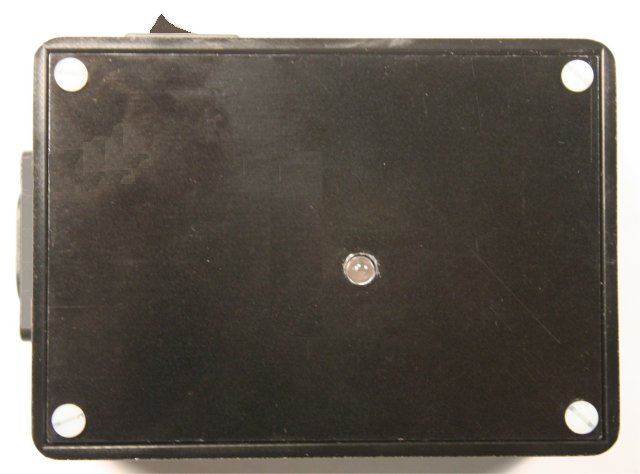
When done, remove the adhesive backing material from the cover. Cover on, secure with nylon screws, apply rubber feet to the bottom.
Performance
To test the regulation, I kept adding 470 ohm resistors in parallel on the output. The output voltage was rock-steady to over 100 ma., dropped to 8.75 volts at 120 ma. I shorted the output, and the short-circuit protection kicked in within 10 seconds--the output voltage dropped to less than a volt. It took about a minute after I removed the short for the resettable fuse to cool down, and the unit went back to normal operation.
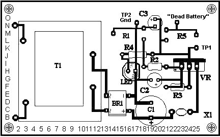
Building The "Deluxe" Version
Here is the schematic:
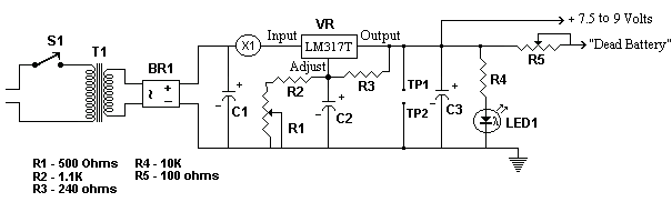
As you can see, it is almost the same as the basic version, except that it uses an adjustable regulator IC and a couple of trimpots to control output voltage and dying battery current. The construction is the same, with a few exceptions to the tooling and assembly. As shown below, I have included a pair of pin jacks so that standard test leads can easily be plugged in.
Clean up the inside of the enclosure with alcohol and you can continue with securing the standoffs and then the fittings.
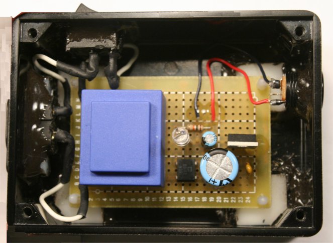
Here is the board layout:
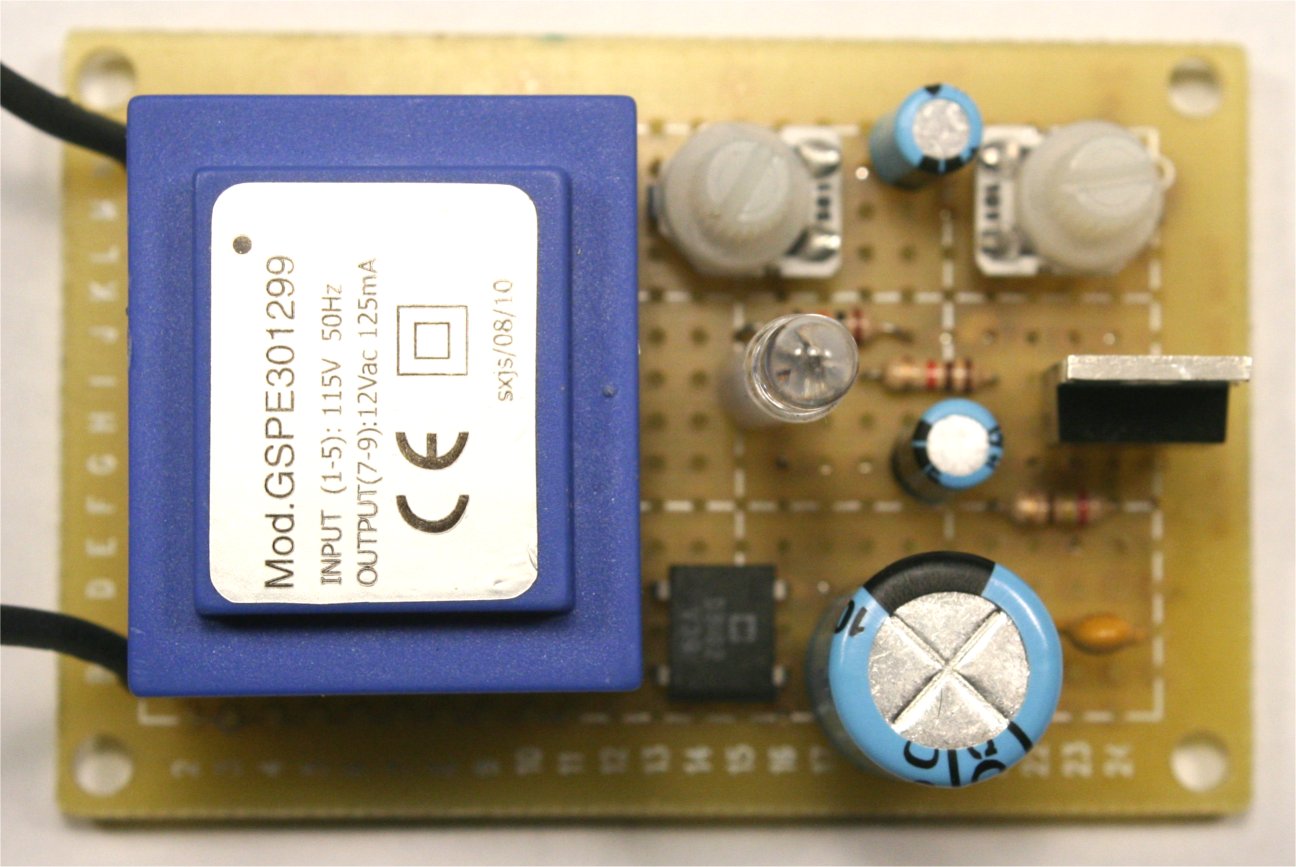
...and a close-up of the stuffed circuit board. In doing this layout, I found a better way to mount the LED. Keystone makes plastic standoffs that will position the LED at exactly the height you want with no fiddling. Their #8340 (Mouser 534-8340) is perfect. If you order the kit, we include one.
Add the leads for output power and AC line connection as described earlier and set up for the preliminary test. The voltage adjust trimpot should be about at its midpoint. When you plug in the power cord (briefly!), your meter reading should be about 8.4 volts. Disconnect power before you continue! If the reading was wrong or there were signs of trouble (like smoke...) check your wiring. If the reading was good, set the trimpot fully clockwise and make sure that you see about 9.5 volts. If OK, disconnect power again, set the trimpot fully counter-clockwise and verify that the minimum voltage is about 7.2.
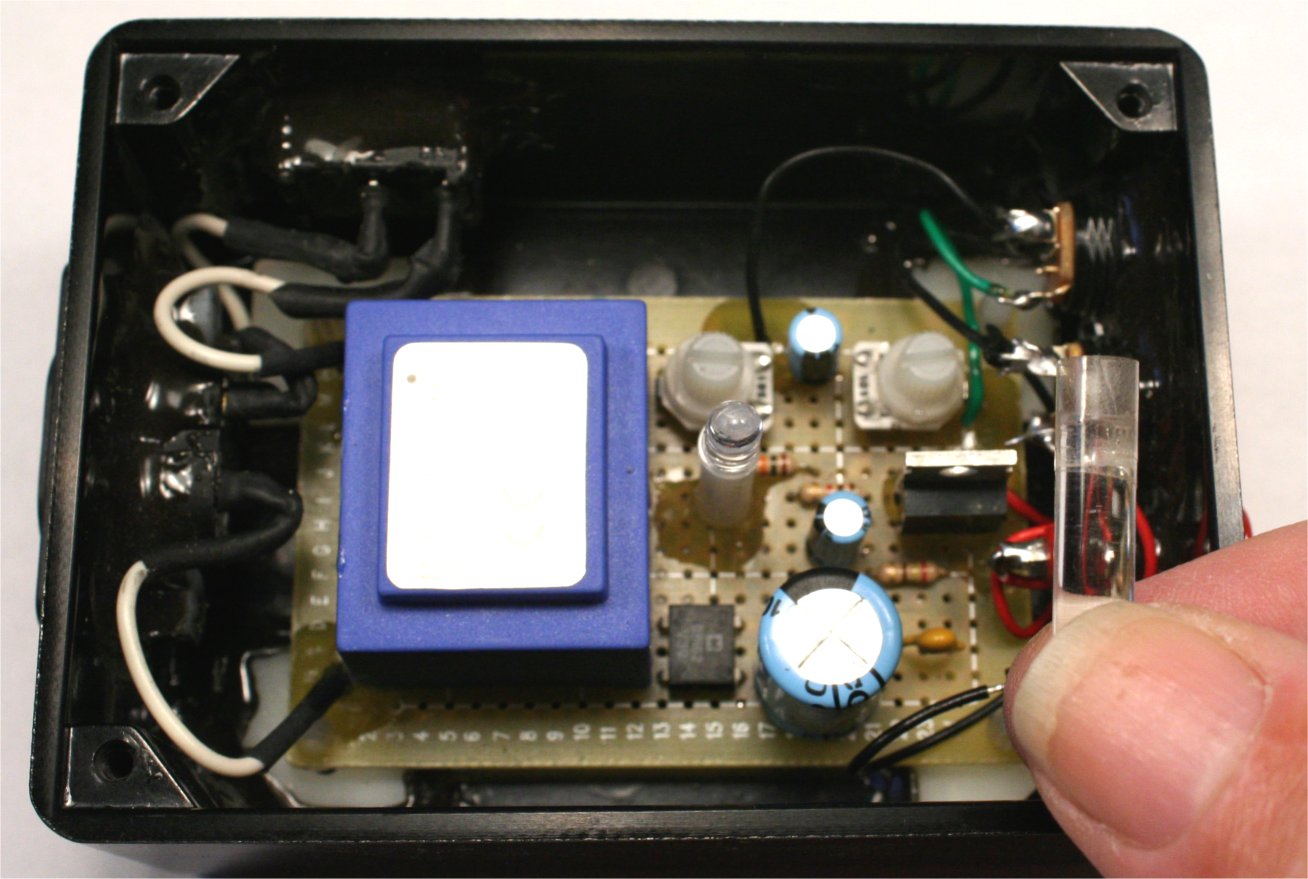
If the voltage tests are good, you can do the final assembly as described earlier. It is exactly the same except that you have to wire leads to the "dying battery" jack and the test points as well as the main output jack. This board is a little tighter than the basic model, so I found it more convenient to add the epoxy beads for strain-relief before pressing the board in place. Use the White-Out trick described earlier to locate the hole for the LED and drill that.
To extend the shafts of the trimpots, I employed short lengths of 1/4" diameter acrylic rod and attached them with epoxy cement. If you buy the kit, suitable material is included. If you are rolling-your-own, PLEASE USE PLASTIC ROD, NOT METAL! You might be able to find a cocktail stirrer of the right thickness.
To center the extension on the shaft, cut a short piece of ordinary plastic tape in half lengthwise and wrap it around the end of one of the rods. Mix a small amount of quick-setting epoxy, put one drop inside the "cup" that you have created, and place carefully onto the shaft of one trimpot. Hold as straight as you can for a bit until the adhesive has set enough to hold on its own. Do the same for the other extension.
When the epoxy has thoroughly cured, use the White-Out trick again to locate holes for the extended shafts. When squaring the cover over the enclosure, use both the corners of the enclosure and the location of the LED as your guides.
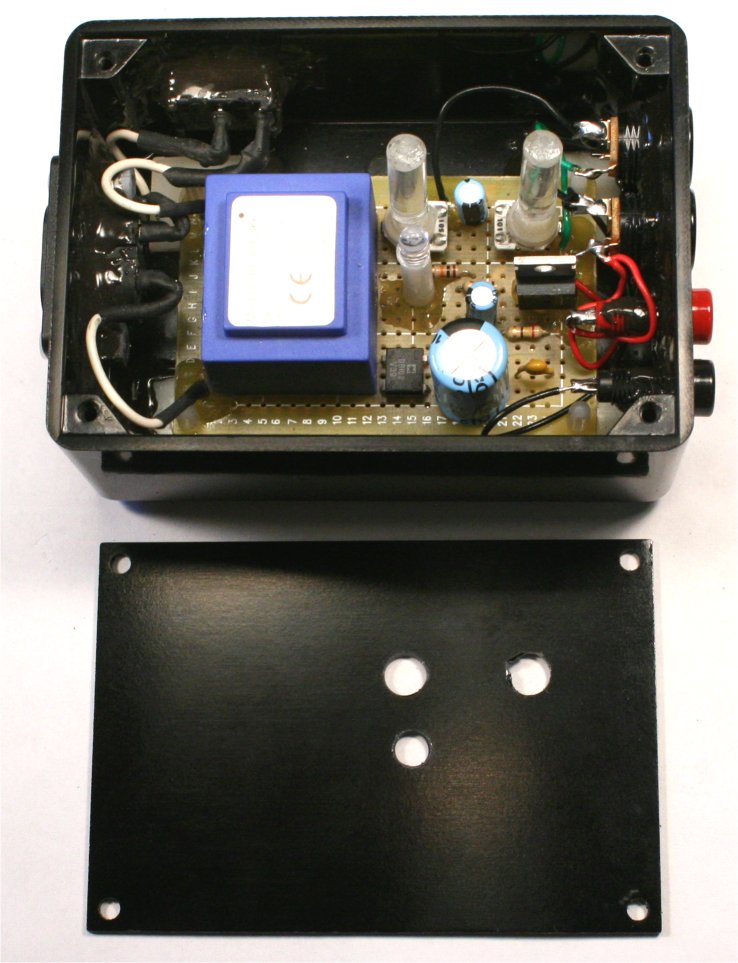
When you pick knobs, be sure that they don't have too wide a skirt; my SKU 0806D fits well. I set the voltage adjust trimpot such that the 12 O'clock position of its knob marks about 9 volts, but this is a matter of convenience and personal preference.
Patch Cords
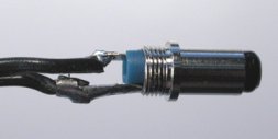
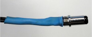
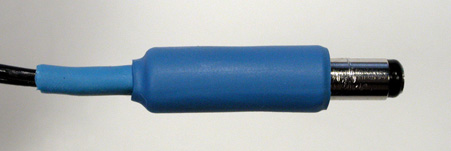
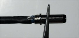
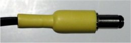
You will want to have a few of these available, usually about 3 feet long. The specified plug has a 2.1 mm inside diameter, and it mates correctly with the output jack shown on the Small Wart side. Depending on what you are powering, you may need a different type of plug on the equipment side. Since I use 2.1 mm power jacks on all my gear, I use the specified plugs and wire them shell-to-shell and center-to-center. The cable is a #22 zip cord that is commonly sold for connecting miniature speakers. Some brands ID the conductors with a stripe on one of the leads, while others have one tinned lead and one bare copper. Musicians will want to ID the plug barrels for easy tracing in stage environments, and this can be arranged either with colored heat shrink tubing or a liquid plastic/rubber coating such as is used to put handles on metal tools.
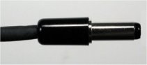
Here are some pictures of the assembly process using the heat shrink method. I used 1/4" heat shrink as an inner "jacket" and 3/8" material as an outer cover over the barrel. I had to ream the barrel out slightly in order to pass the 1/4" material through the rear hole.
To use the liquid coating, I slipped a 1" length of heat shrink over the strain relief of a plug. Then I assembled the plug (pulling the heat shrink out the end with chain-nose pliers), cleaned it with a little alcohol, dipped and hung it according to the manufacturer's instructions and let it harden overnight. Cut off the closed end, and you have a professional, close-fitting result.

|
|
SBE SKU |
Other
Part Numbers |
| Common Components - Both Models | ||
|
Case |
0306N |
|
|
Pad-Per-Hole Perfboard |
|
|
|
T1 - Transformer, 117 V to 12 V |
2400H |
|
|
LED1 |
2302 |
|
|
DC
Power Output Jack, 2.1 mm center |
0611 |
Mouser 163-4302 |
|
|
|
|
|
BR1 - 50 PIV Bridge Rectifier Module |
2200 |
Mouser 583-DB102 |
| S1 - SPST Rocker |
0224P |
Mouser 540-SRB22A2DBBNN |
| AC Power Inlet |
|
Schurter, Mouser 693-4300.0096 |
|
AC
Power Cable |
0624 |
Mouser 173-21101 |
|
DC
Power Plugs, 2.1 mm center |
0613 |
Mouser
1710-2131 |
| 4-40 x 3/8" Nylon Screws (4) for cover |
8015L |
|
| 4-40 x 1/2" Nylon Screws (2) for inlet |
8015L |
|
|
4-40 x 1/4" threaded studs |
8015O | |
| Nylon PCB Standoffs (4) | 0414 |
Mouser 561-LAD187 |
|
Heat Shrink Tubing - 1/8", 3/16" |
||
|
Hookup wire |
|
|
|
Rubber
feet |
0318 |
3M SJ-5312CL |
|
#22 gauge zip cord |
0511 |
|
| Parts For Basic Version | ||
|
C1
- 1000 mfd. 35 volt radial electrolytic |
|
|
|
C2
- 10 mfd. 16 volt radial electrolytic |
|
|
|
VR
- 7809 Voltage Regulator |
|
|
|
R1 - 1K to 18K (See Text) |
0900, etc. |
Mouser 291 series |
| Parts For Deluxe Version | ||
|
C1
- 1000 mfd. 35 volt radial electrolytic |
|
|
|
C2, C3 - 10 mfd. 16 volt radial electrolytic |
|
|
|
VR - LM317 Voltage
Regulator |
1804 | |
| R1 - Semi-fixed trimpot 500 Ohms | 1015A | Mouser 323-409H |
| R2 - 1.1K | 0900, etc. | |
| R3 - 240 Ohms | 0900, etc. | |
| R4 - 1K to 18K (See Text) | 0900, etc. | |
| R5 - Semi-fixed trimpot 100 Ohms | 1015A | Mouser 323-409H |
| Tip Jacks | 0618J | |
| Knobs (2) | 0806D | |
| Shaft Extensions (2) |
I hope you find the Small-Wart a useful addition to your gig-bag and shop. Comments and suggestions are welcome at smallbearelec@ix.netcom.com.