|
The Velleman K8094 is billed as an "Extended Record/Playback Module". As
such, it has a socket and support circuitry for an ISD17xxxPY "Chipcorder",
in effect about 75% of what is needed to build a serviceable looper for
practice, studio or stage use. I started with what the module offered and
designed around it a simple buffer/mixer that provides connections for my
guitar and amp. Because this project involves a fair amount of hacking, I
don't recommend it for a beginner. Accordingly, I'm not describing the
construction in nearly as much detail as some of my "breadboard-to-box"
designs. If you tackle this one, you must have enough experience to be able
to work from my outline and notes. |
|
|
|
What Is On The Board |
|
|
|
|
|
|
|
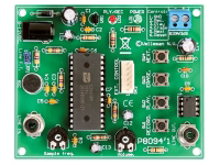
Referring to the Velleman schematic, the ISD17xxxPY chip series will store
up to 480 seconds of audio. Exactly how much depends on the chip and
the A-to-D sampling rate set by on-board trimpot RV1. The higher the
sampling rate, the better the sound quality but the shorter the record
time. The kit includes an ISD17240PY, which will handle 240 seconds at an 8
KHz sampling rate--adequate for music IME. Any chip in the series can be
substituted with no change to the board. Audio input can come either from an electret microphone cartridge
(included with the kit) or through the Line Level input to pin 9. With pin 22
grounded (header connection provided on the board), the chip records from
the Line Level input. With pin 22 floating, recording is from the balanced
microphone input.
Though I did not use it, the board provides an LM386N amplifier for
driving a small speaker. It also has connections for Power and Record/Play
LEDs and its own voltage regulator and filter; an ordinary 9- or 12-volt DC
wall wart is fine for power.
The record, play and erase functions are activated by simple contact
closures. Mounting pads are available for the on-board tactile switches
provided in the kit. But the same connections are also brought out to an
on-board
header, and the kit includes a cable assembly that I found convenient for
connecting to stomp switches.
|
|
 |
|
Making It Into A Looper - and How It Works |
|
|
|
|
|
|
|
Q1 is a JFET (can be any common type) set up as a source-follower--no gain,
but it presents a high input impedance for your instrument, keeps it from
being loaded and isolates it from the stages following. The output of Q1
drives two amplifiers. Record buffer IC1-a couples the guitar signal to the
Line Level input on the main board, and potentiometer R5 allows adjusting
the level of what is recorded. Potentiometer R2 serves as the Source load
for Q1 and also provides a separate, adjustable-level signal to the playback
amplifier IC1-b. In playback mode, this is what allows you to play along with whatever audio
is coming from Line Out.
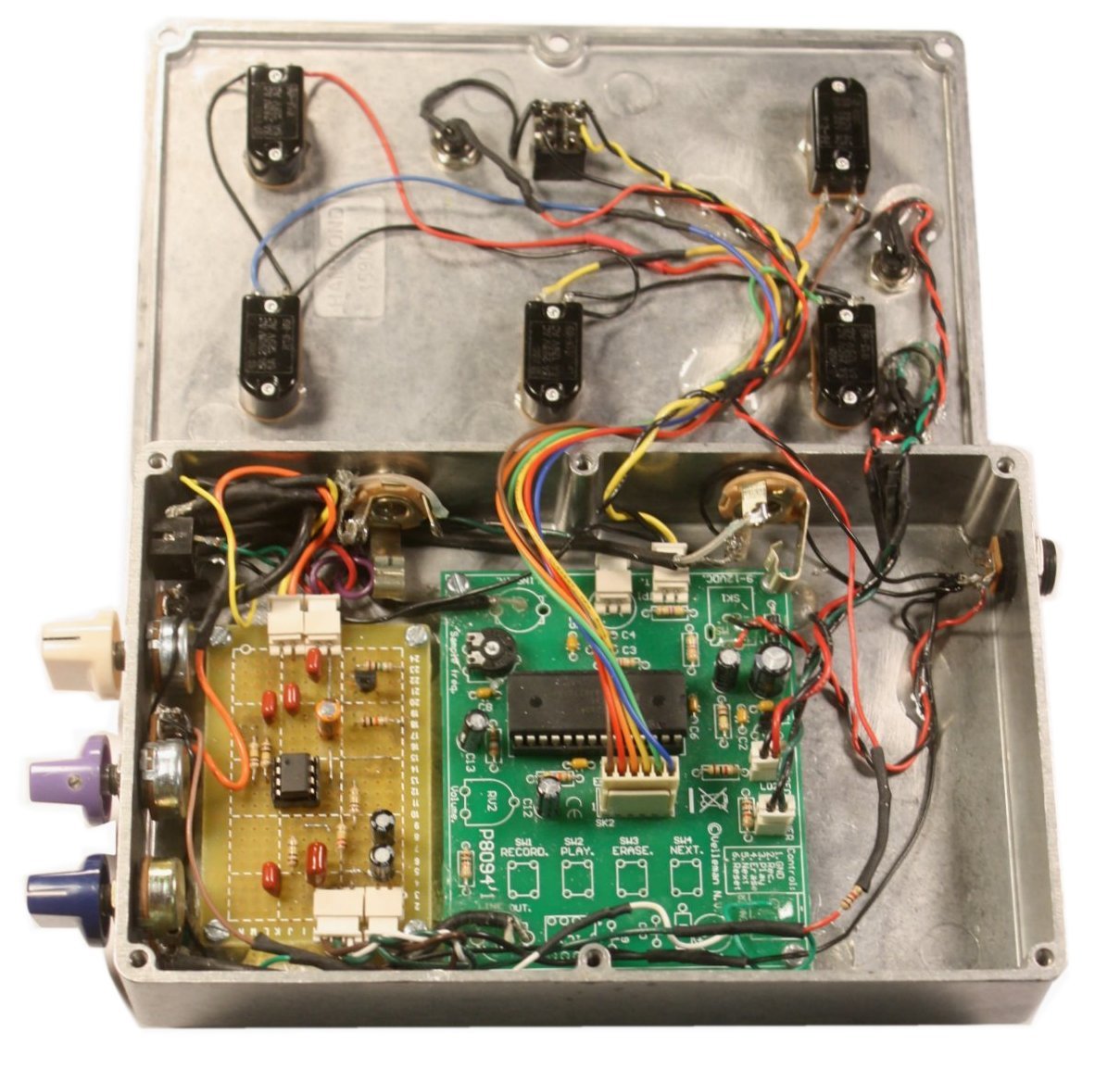
I built the mixer on a medium pad-per-hole perfboard and married it to
the main board with a few Molex connectors. Here is the result: |
|
 |
|
 |
|
Construction Suggestions, Ideas and Notes |
|
|
|
The enclosure shown is a 1590DD.
The electronic design lends itself to building and testing one section at a
time, especially if you connect with Molex headers and plugs as I did. Where
the pre-terminated 3
1/2" wire that I stock was not long enough, I added wire of the same color
and covered with heat-shrink. It adds some cost, but the convenience is
completely worth it, IMO. |
|
|
|
I started by stuffing the main board according to Velleman's instructions
and making sure that that much worked with the provided electret mic
cartridge. I actually built the whole PCB with the integral speaker
amplifier, but I wound up removing those parts later when I figured out that
they would not be needed. I suggest leaving out the LM386N and associated
parts. In place of the on-board DC power jack provided, I used a standard
panel-mount type with external nut. Again, a matter of convenience because I
was designing some as I built. At least temporarily, you would also want to
connect the power and record/play LEDs. With the PCB stuffed, for test purposes, wire a 100K
audio taper pot from Line Out to ground as a level control and connect this
output to your amplifier temporarily. Turn up the level control and your amp
volume just a little and try the controls for Record, Play and Erase. You
don't even need to connect switches yet; use that nice plug that you are
given and connect an alligator lead to the ground lead pin 1 (brown).
Touching this to the other control leads will work fine. If you get action,
proceed. If not, first figure out where you made a mistake with the PCB. |
|
|
|
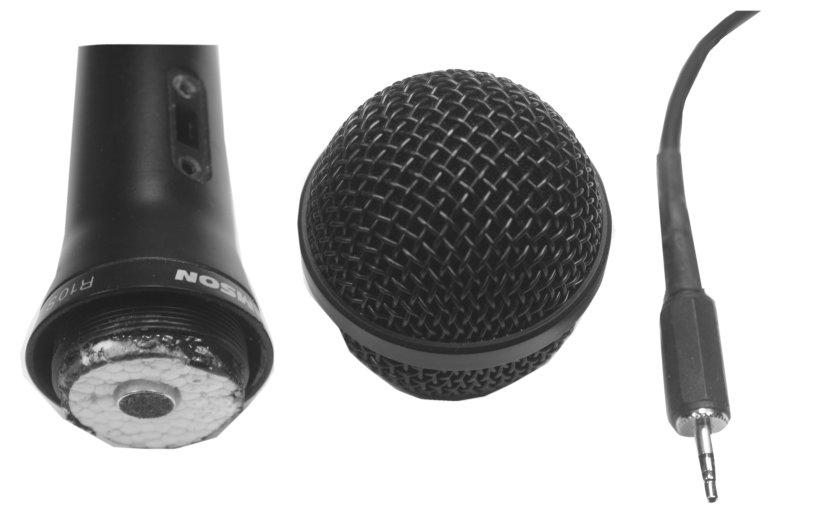
Call me crazy; I was determined to make use of that electret cartridge
and turn it into something that I could put on a stand. So I bought the
cheapest dynamic mike I could find, removed the element and cobbled the
cartridge into it. A piece of styrofoam holds it in place. This kind of
device is meant to feed a balanced input, not seeing ground, so I wired to
it the tip and ring of a pre-fabbed stereo cable. This mates to a
panel-mount stereo jack, and the T and R then feed the mic + and - on the
board. |
|
|
|
|
At this point, I located and glued down studs for the main PCB. If you use the
same enclosure, refer to the pic above for positioning. |
|
|
|
With the board mounts solidly in place, I planned out the connnections that
I would need to controls, LEDs, jacks and the mixer board. As I noted
earlier, I used Molex headers where it was convenient to do so. To get to
the +9 and + 5 rails, I bored out the holes on the PCB that were intended
for a speaker connector and ran #24 stranded wire through. I used shielded
cable for the connections to Line In and Line Out, but this may not be
absolutely necessary...YMMV. |
|
|
|
With the PCB screwed down temporarily, I located the holes for the output
jack to the amp, dc power jack and mike input, drilled those and mounted the
hardware. Now I was able to power up, record from the mike and play back before going further. Then I located studs for the mixer
board and glued those down. With the blank board in place as a guide to
positioning, I tooled the cover plate for the stomp switches and LED
holders. |
|
|
|
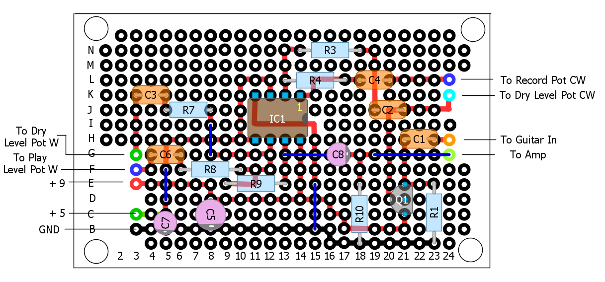
Here is a layout for the mixer board. I chose to build and test one stage at
a time, starting with the playback amplifier. I laid down and made
connections for the power supply busses and ground and wired IC1-b. Then I
tested that much with the mike. Next, I located and drilled the hole for the
guitar input jack, wired the buffer and made sure that I could get dry
signal through the amplifier. The record amp came last. |
 |
|
|
|
I have been having a lot of fun with my looper, and I am sure that you'll
enjoy building and using your own. Comments and suggestions are welcome at
smallbearelec@ix.netcom.com. |