The Fuzz E-One
By Steve Daniels, Small Bear Electronics LLC
© 2011 By Small Bear Electronics LLC
 The Gibson/Maestro FZ-1 is often called the "Satisfaction"
Fuzz, because Keith Richards used it to create that memorable lick. The later
FZ-1A used the same circuit with different transistors. The
Fuzz-A-Tort was an almost identical circuit that was the basis of a kit offered
by Sentry Manufacturing Company. It appeared in an article in the Jan.-Feb. 1968
issue of Elementary Electronics, and I happily recall building that during my
college days.
The Gibson/Maestro FZ-1 is often called the "Satisfaction"
Fuzz, because Keith Richards used it to create that memorable lick. The later
FZ-1A used the same circuit with different transistors. The
Fuzz-A-Tort was an almost identical circuit that was the basis of a kit offered
by Sentry Manufacturing Company. It appeared in an article in the Jan.-Feb. 1968
issue of Elementary Electronics, and I happily recall building that during my
college days.
I remembered these pedals as giving a harder, more aggressive distortion than the Fuzz Face, but I never succeeded in cloning them until I had the help of Gez Paton's notes on the transistor "recipe." As it turns out, the circuits were designed to be friendly to the typically very leaky germanium transistors that were available at the time. If you have thrown all of your "too-leaky-for-a-Fuzz Face" parts in a drawer in your shop, you can use them to make a really distinctive-sounding distortion for very little money.
This article describes the construction of my perfboard clone, which I call the Fuzz E-One. The project is suitable as a second or third build for a careful beginner. You must have a drill, and a Dremel tool is extremely helpful. I have done a "build-it-this-way" recipe, including the tooling for a two-knob shell in a 125-B enclosure with board-mounted jacks and pots. While this forces the builder to pay very close attention to locating the holes, the result is a board that drops into place and is very easy to set up. I have not changed the circuit, and I have updated those aspects of the original pedal that would trouble a modern player; this version is true-bypass/NPN/negative ground, includes a voltage regulator to allow the circuit to run from 9 volts, has a DC power jack and an in-use LED. Audited 3-transistor sets (NPN and PNP) are available in the Stock List. For those who wish to roll-their own, the setup notes cover selecting devices and tweaking the bias.
The FZ-1A
Here's the original circuit. The FZ-1A used PNP 2N2613 or 2N2614 transistors and was powered from one AA penlight. The FZ-1 used PNP 2N270 transistors in the same circuit with different resistor values and required two penlights.
How It Works
Q1 is an emitter follower that provides a high input impedance to match a guitar. Some on-line references say that this stage is not necessary. By all means check this out on a breadboard if you want to--YMMV.
Q2 is forward-biased partly by R4 and partly by its internal Collector-To-Base leakage current. Potentiometer R6, together with resistors R5 and R7, determine how much Q2 is "On," and so the signal level at the Collector. Q3 is forward-biased by its leakage current, and R9 determines how much it is "On." This stage distorts more as the level of the input signal from Q2 increases.
The Fuzz-A-Tort
Here is the schem of the Fuzz-A-Tort. As you can see, it's the same basic idea, but with a different biasing scheme for Q2. I have tested several sets of transistors in both circuits, and I found that they work equally well with either biasing scheme.
The Fuzz E-One Small Bear Clone - Schematic
Schottky diode D1 provides reverse-power protection with minimum voltage loss. The combined forward voltage drops of D2 to D4 give the right voltage to simulate a "hot" penlight battery, and the voltage will remain stable as the battery ages. Different combinations of germanium and silicon diodes can be used if you want to experiment with higher or lower voltages, though I strongly suggest doing that on a breadboard.
Other schematics recommend audio taper for both pots. I got better sweep of the fuzz with linear taper for the Fuzz pot...YMMV.
Construction
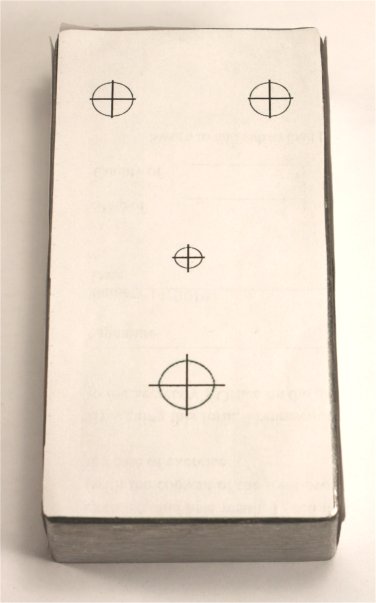
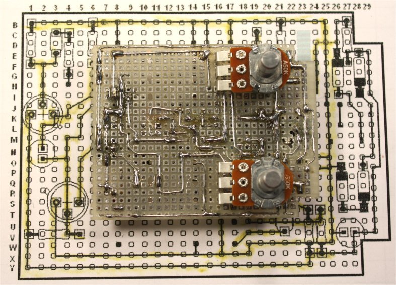
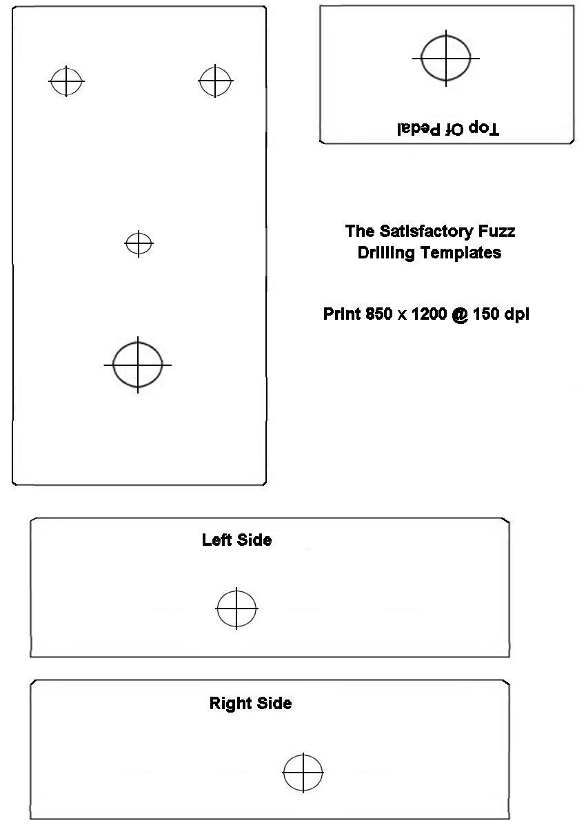
Download the template file and print out the templates. The actual size of the JPEG is 1200 x 850 pixels, so you may need to re-size it to those dimensions. I printed at 150 dpi.
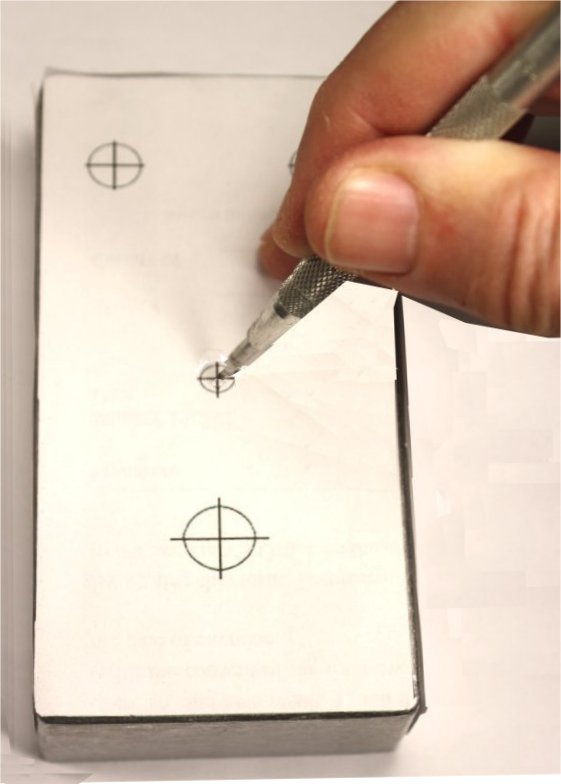
Remove the four screws that secure the lid to the enclosure. With a good, sharp scissor, cut out the template for the top. Attach a couple of pieces of double-sided clear or masking tape to the box, and carefully center the template on the cover. In the same way, attach the templates for sides, being careful to get the holes for the jacks in the correct locations relative to the the switch and the pots. The output jack is on the left as you look at the front of the pedal and input is on the right. Now use a scribe or scratch-awl to put a small dent at the center mark of each hole.
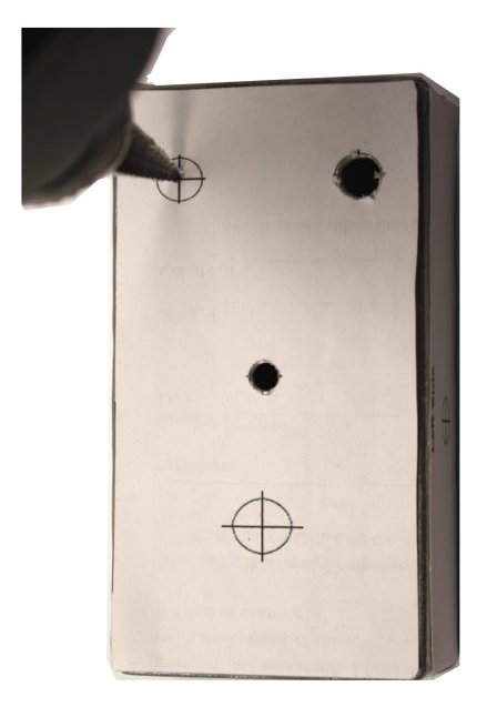
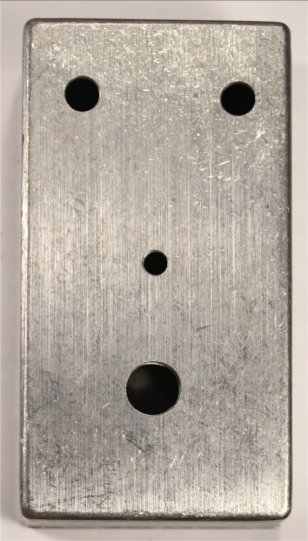
The holes for the potentiometers are 5/16", and the holes for the input and output jacks are 3/8". The hole for the DC power jack is 7/16" and for the stomp switch 1/2". If you don't use a bezel for the LED, its hole is 7/32". Many people like to use a step drill (the Irwin Unibit is a popular brand) because it does a quick, clean job of boring any size hole from 1/8" to 1/2". If you use standard twist drills, bore a 1/8" pilot hole, enlarge with a ¼" drill, and then use a tapered reamer to slowly bring each hole to its final size.
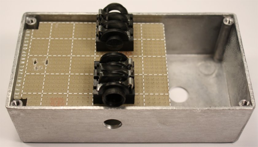
Because we are using board-mounted pots and jacks, studs to secure the circuit board are not needed; the board will rest on, and be held in place by, the pot and jack contacts. At this point, we will cut the perfboard to size, do a little tooling, and "mock-up" the assembly to ensure that the registration of the holes is correct.
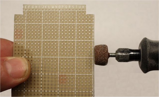
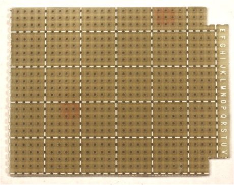
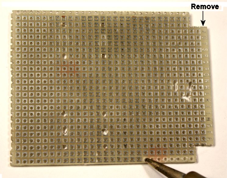
To start, cut the board 24 holes wide by 30 long. If you are using one of my large pad-per-hole boards or the Radio Shack p/n 276-158, the pics show exactly where to slice it and leave margins.
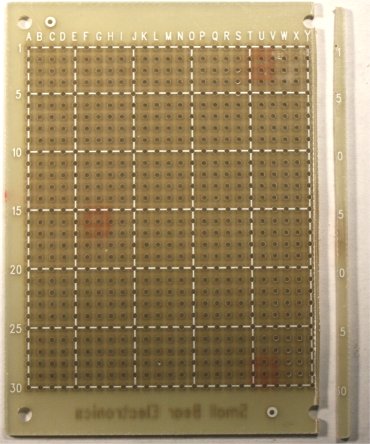
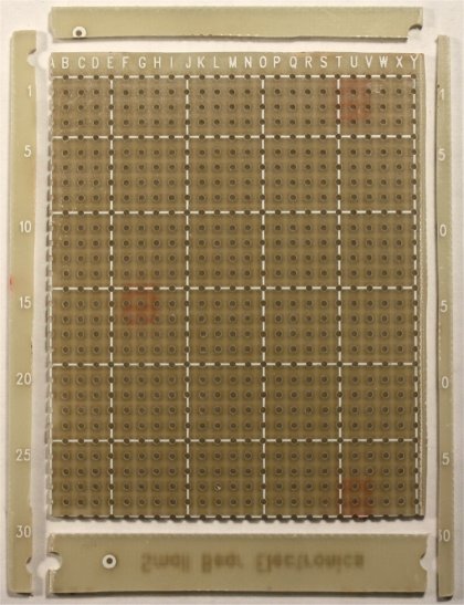
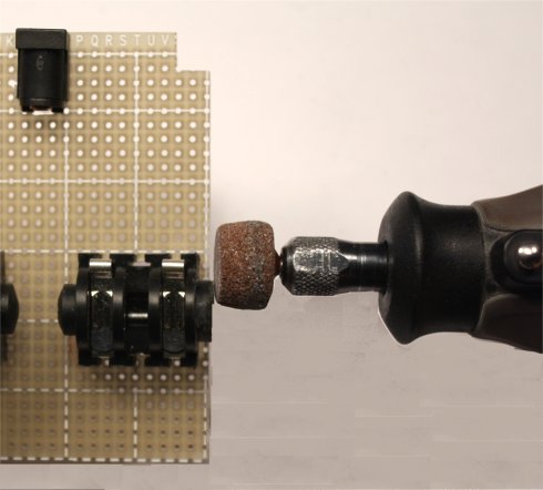
I did this job with an abrasive cutoff wheel in a Dremel handpiece. If you go this route (and I recommend it, with appropriate caution,) keep in mind that abrasive cutoff wheels are inherently dangerous! In cutting FR-4, they throw off particles of fiberglass and abrasive. When they break, and they do, the pieces fly like bullets. You MUST wear eye protection and a dust mask when using them. Finish the rough-sizing by cutting out the sections that will abut the screw-posts. You should have something that looks like the right-hand pic, whose width does not quite make it into the enclosure.
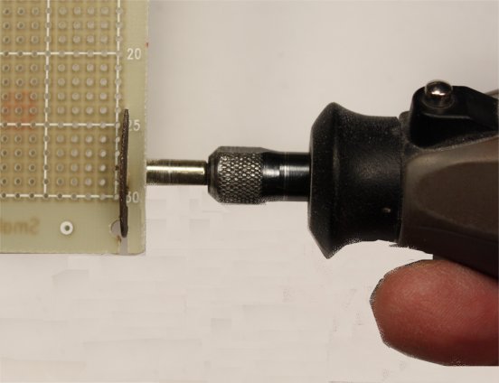
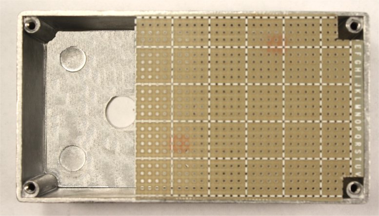
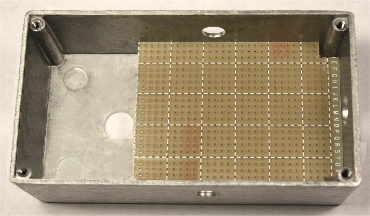
Now slowly grind down each long-side edge. You can do this with a file, a Dremel grinding stone, or even a sanding block. Take out all the material above the top index line. Leave a small margin below the last index line on the bottom. Work slowly and evenly to the point where the board can wedge in place about 3/8" above the floor as shown in the lower right-hand pic. Did you notice in doing this job that the sides of the enclosure slope slightly? That was deliberate in manufacturing, because otherwise it would not have been possible to release the box from its mold cavity.
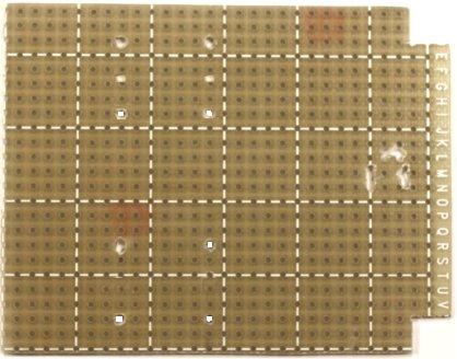
The next step is to cut slots for the contacts of the DC power jack and drill holes for the pins of the input and output jacks. I used a fine (#63) drill bit as a router to do the slots and a #57 to enlarge the holes in the board to admit the jack pins. Refer to the left pic for the locations. Take your time, and be sure to get these right!
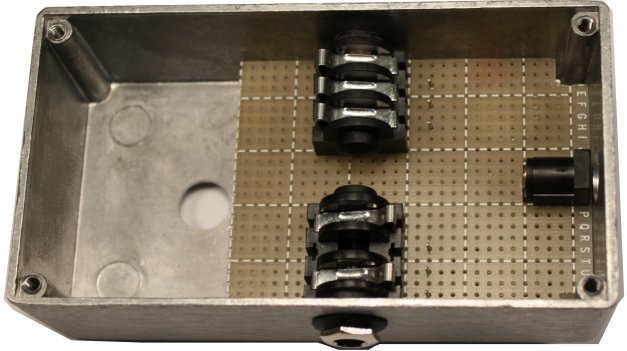
Now we can start to mock-up the mechanics. Slip the pins of the jacks into their correct holes, and set the board in place as in the right-hand pic. The board won't go down in yet, but you can make sure that the horizontal registration of the jacks is correct with respect to the holes in the side.
If all good so far, use a grinding stone or file to take off just a tiny bit of material from the front of each jack--only enough so that the board will drop down easily to the level you established earlier. You might also have to grind a little more from one or both edges of the board if the assembly still binds on the way down. With the board parallel to the floor of the enclosure, the holes on the side walls of the must line up correctly with the openings of the jacks.
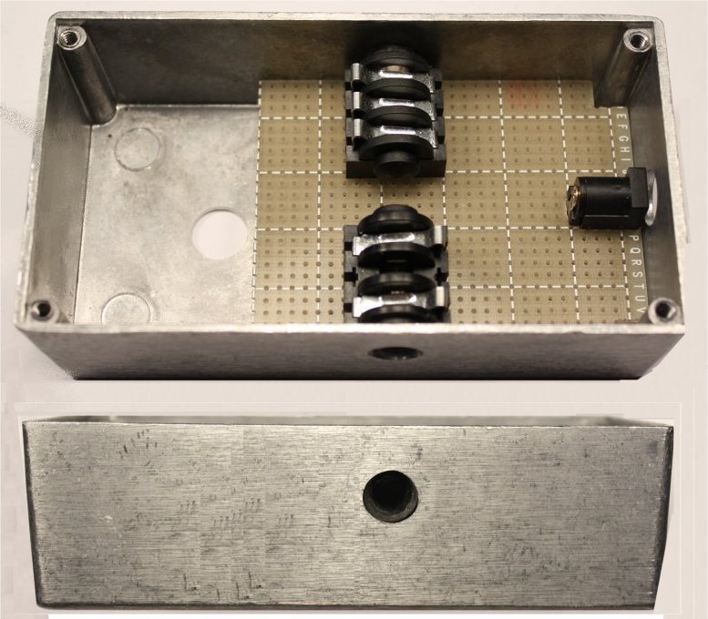
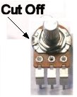
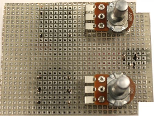
Remove the assembly momentarily. Cut or bend the locating tabs off from the potentiometers and set the pots in place in column 17 of the board. Set the whole assembly in place again, screw the chrome ferrules into the jacks and ensure that nothing binds and everything is lined up as in the right-hand pic.
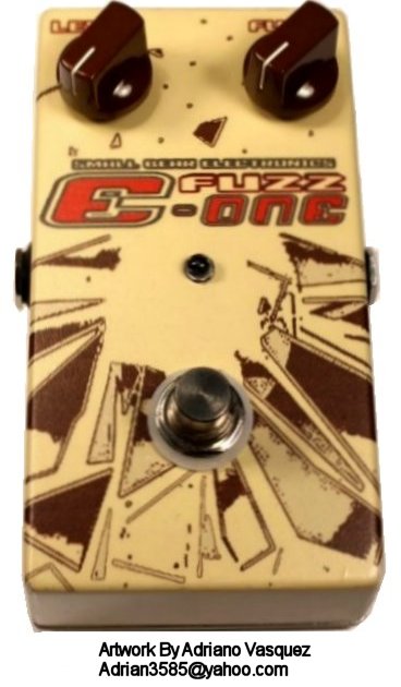
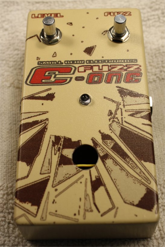
If everything is OK to this point, disassemble the mock-up. Now is the time to paint and decorate the enclosure. The design shown in the lead pic was done on inkjet decal stock by my assistant, Adriano Vasquez.
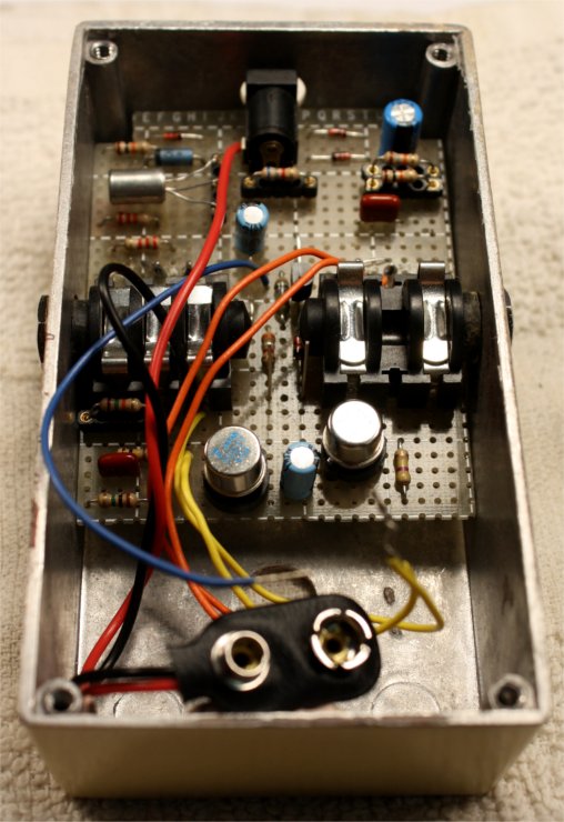
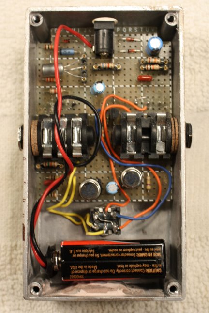
Stuffing The Board
The solder pads on pad-per-hole board make stuffing and wiring easy. However, sometimes a pad has to be removed in order to avoid potential short circuits. This is easily done by heating the pad with the tip of a soldering iron until its adhesive bond breaks. The pic shows the beginning of the process, and the drawing below shows the pads that I removed. If you are using my large board, remove the lettering on the right, because you will need that column free for a wire run.
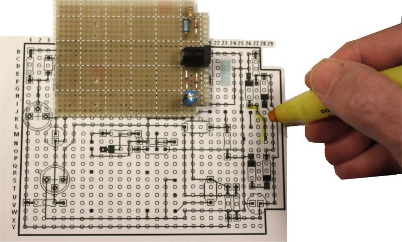
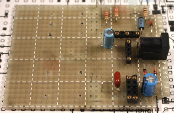
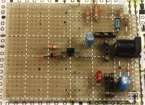
If you have never hand-wired on perfboard, take a look in my article on the Tweak-O; the technique is the same. The layout drawing follows. I began by stuffing and then wiring the voltage regulator section, and I suggest that you follow suit. This will start the power and ground busses and give you good physical references for locating the rest of the components.
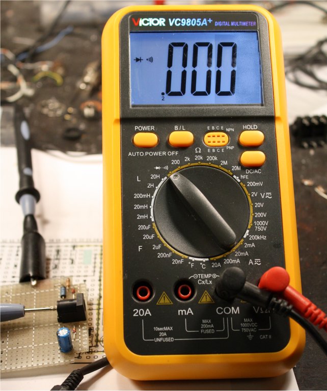
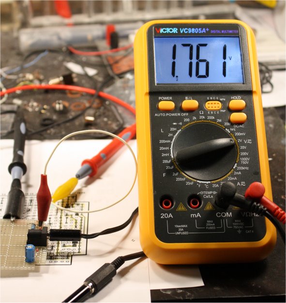
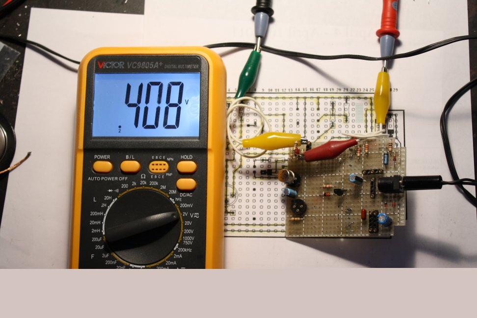
As always, I strongly suggest making a clean copy of the layout drawing and marking off connections with a yellow highlighter as you make them. Then set your multimeter for continuity and make sure that the points you have just connected really are! When you have finished stuffing and wiring the power input and voltage regulator, connect a power supply: regulated 9 volts, not an unmodified wall wart!, and center negative, please. Make sure that you have roughly +1.7 volts on the supply bus. The exact reading will depend on the combined voltage drops of the diodes in your string. If you don't see close to that, check your wiring Now, and find the problem.
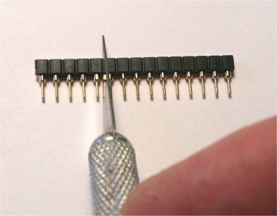
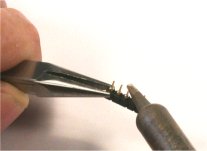
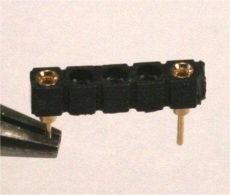
If everything is OK to this point, continue to stuff and wire. You will need a few lengths of in-line-socket material for the bias resistors and transistors Q2 and Q3, so you may want to create those now. To cut single- in-line socket material to length, score about a dozen times in the groove between the pins with an X-acto or similar knife and then snap off at the score line. Then remove unneeded pins by holding a soldering to the bottom of the pin and pressing gently till it falls out. Make four lengths of five pins like the one shown on the right, and a similar length for Q3 but with pins in the left, right and center holes.
I stuffed everything to the right of the potentiometers and created the above-board jumpers for those. The pots get installed later, before testing. Continue by adding the LED driver circuit. Test continuity point-to-point before you proceed!
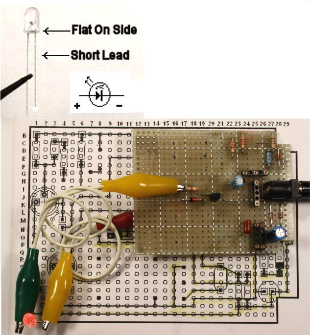
You can now test the LED driver circuit, and by extension the power wiring. Use a couple of alligator leads to temporarily connect the LED. The cathode (short lead) connects to R14. Connect your power supply, and the LED should light. Grounding the LED control point (Base of Q4) should turn it off. If the driver circuit doesn't work, check your wiring before you proceed.
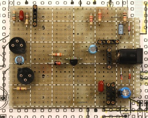
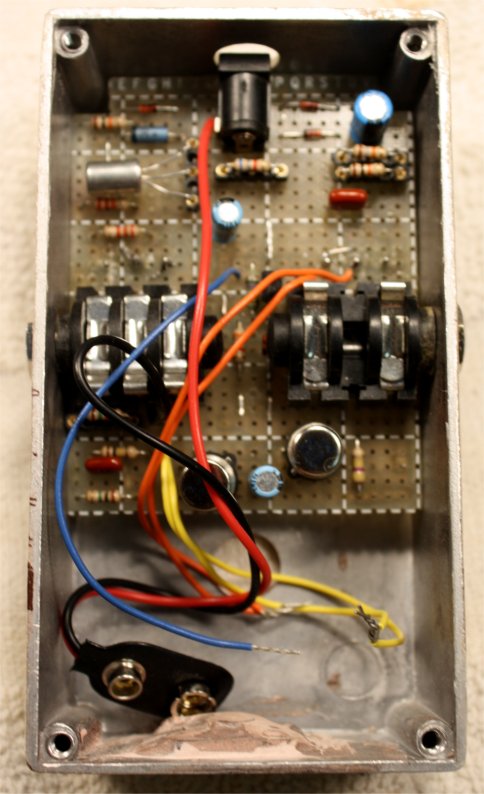
Don't install the jacks yet; the assembly is easier if you stuff the right-hand section of the board, wire it, and then wire the connections with the left-hand side. Pay close attention to the wire routing! If you screw this up, you can find yourself having to unsolder a run because you have covered a hole for a component pin. Install the potentiometers. The board is almost finished, and you are ready to line up the transistors. When selecting the devices...
Part Numbers Don't Matter!
Any that you would look to for germanium Fuzz Faces are candidates, but you want to sort for the ones that are either high-gain and too leaky or not leaky but too low in gain. This is completely counter-intuitive if you are used to doing FFs and Rangemasters, but this is Not the FF; the circuit was designed to expect, and like, leaky parts, at least for Q2 and Q3. If you have been building lots of Fuzz Faces and Rangemasters, this probably describes what's in your "junk" bag. Beginners: If you don't want to buy one of my tested sets, ask in the Forum at diystompboxes.com. Many people there will have a bag of "rejects" that they thought they would never use, and they will probably be glad to be able to sell some.
NB: The gain and leakage figures following are based on 9 Volts Collector-To-Emitter as though screening for Fuzz Face devices. Out of curiosity, I also did the measurements with 1.5 Volts C-E. Leakage goes down maybe half, but leakage-adjusted gain drops right off a cliff. I am not sure what this means and would welcome comment from someone who knows more transistor theory than I do.
Q1 can be one of the devices from a "low-gain" assortment. Gain need not be higher than 60s, and those parts are often low-leakage, which is what matters for the first-stage emitter follower.
Q2 can be a typical "Good For A Fuzz Face" device, though the standard bias resistors allow for more leakage than you would normally want in Fuzz Face/Rangemaster germanium. I have tried gains from 75 to 250 and leakage up to 500 microamps with good results.
Q3 needs to be a medium-to-high-gain part that leaks at least 350 microamps if it is to bias as the designers intended. I have successfully used devices that leak more than twice that much. We have lots of these that we purposely don't sell for Fuzz Faces, and they are absolutely perfect here.
Tweaking It
In describing this process, I presume that you are working with devices that you have found yourself and have tested for leakage and gain. If you are using one of my sets, you will know what the required resistor values are. However, do go through the process anyway to confirm the measurements that come with the set.
Install Q1 and Resistor R4 and connect your power supply. Start with R4 at 10K if Q1's gain is in the 60s. Start with a lower resistance if the gain is higher.
Note that if you use bare fingers when socketing the transistors, your body heat will drive the leakage out of sight and you'll wonder why the circuit does not work on power-up. After inserting a device, wait at least 5 minutes before you tweak or take measurements.
If Q1 isn't leaky (say less than 150 microamps) and has a gain in the 60s to low 70s, the voltage at the emitter should be .4 to .6 volts with R4 at 10K. If the gain is higher or the device is more leaky, you may use a lower resistance to bring the voltage within range. Lower-gain devices that put the emitter voltage at .2 to .3 volts can also be used; they work, but the maximum fuzz does not sound as deep.
When you have Q1 set up, disconnect power and install Q2 and R9. Start with the nominal value of 10K.With power applied and R6 at maximum resistance (maximum fuzz,) pick a value for R9 that puts about 1 Volt on the collector of Q2. Raising the resistance will lower the voltage and vice-versa. R9 will vary a lot depending on the gain and leakage of Q2.
When you are satisfied with Q2, plug in 10K resistors for R10 and R11 and a device for Q3. Apply power and measure the collector voltage. I have sorted numerous devices for this position by leaving R11 at 10K and selecting R10 to put .6 to .8 volt on the collector.
I have lined up numerous sets by this procedure with very good results. I did notice that very leaky devices (over 500 microamps) can be hard to line up in the Q2 position; save those for Q3. If you can't get a particular stage to line up, re-check the leakage and gain of the device, and consider that you might have a wiring error to find. Once all the devices are biased correctly, you can install the jacks, do some of the final wiring and have a first listen.
Solder connecting leads a few inches long to the input jack tip, the output jack tip, the circuit input and the wiper of R12. Then temporarily connect input tip to the circuit input and output tip to the pot. Connect your guitar, an amplifier and a power supply.
If you don't get fuzz, this is the time time troubleshoot. I have discussed standard techniques in other articles, and they apply here. The drawings have been carefully vetted, so you need to find out where your work differs from them. Start with clean copies of the layout and the schematic, and re-trace everything you have done with the continuity scale of your meter until you find all the bugs.
Final Assembly and Wiring
As always when working with a decorated enclosure, remember that this is a time for patience and moving slowly, especially when you have a tool in your hands. Put a towel or other soft cloth on your bench to protect the finish while you work.
Refer to the layout drawing to solder in the battery snap and add the lead for LED control. Slip the LED into its holes in the board, remembering that the short lead goes to R14, but don't solder it in place yet. Now set the board into the enclosure and wiggle the LED into place in its mounting hole. Install the ferrules for the jacks and the hardware for the pots finger-tight. Adjust the LED to the height you want on the front, put a right-angle bend in each lead to fix the height and then cut the leads down.
Remove the hardware, remove the board and solder the LED in place. Install two fiber spacers onto the input jack and the output jack and attempt to set the board in place again. I found that I needed to thin the washers on the output side using a Dremel grinding stone to get an exact, snug fit. Before installing the stomp switch, tighten down the hardware and test again with guitar and amp connected to make sure that nothing got shorted or broken in the mounting process. Do this with both battery and power supply.
Install the stomp switch and wire it according to the notes in the layout drawing. Test again with your equipment.
Got the effect? If so,
CONGRATULATIONS!
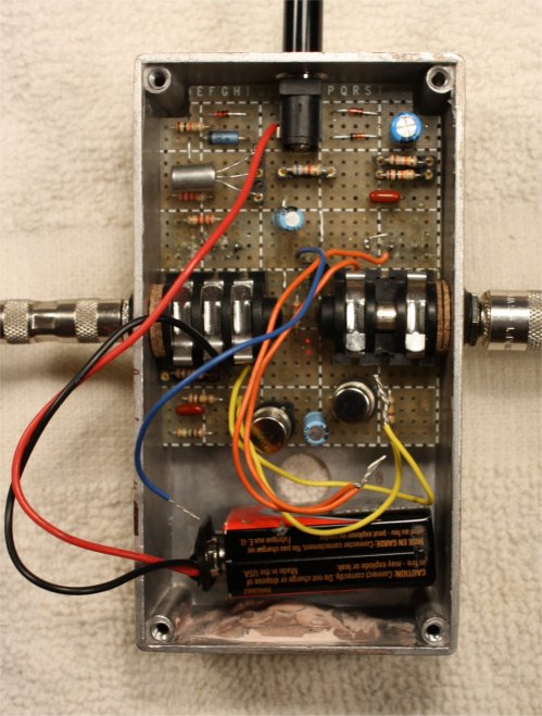
You may want to add a battery clip and tack down the snap with a bead of epoxy before buttoning up. I hope you enjoyed building the Fuzz E-One, and your feedback and suggestions are welcome at smallbearelec@ix.netcom.com. For those of you who are not comfortable with the amount of tooling needed, I will be getting a printed circuit board made in the next few months.