Thoughts On Designing A Pedal "Shell" and
Creating Paper Drilling Templates
© 2012 By Small Bear Electronics LLC
One of the questions that novice builders frequently ask is: "How do you
design a housing for a pedal?" This article isn't an exhaustive treatment
either of the design process or of the tools and techniques involved; that's
really a number of separate articles and/or books. However, since I recently did a mechanical
re-design of my Wild Mouse, I'll take the opportunity to show you some of my
thinking process for this particular job. The details may well be a little different for your build, but
the ideas will probably be helpful to people who are contemplating their first
self-designed work.
I had designed rev 2 of the Wild Mouse as horizontal with the pots on the
long edge of the enclosure:
 |
I had good reason for doing it this way at the time: I didn't have pots smaller than 16mm
diameter, and putting four on the narrower side of the enclosure would have
meant squeezing the knobs closer than I would have liked--I'll show you that
later. Once I had more
choices of components, I wanted to re-orient the build from horizontal
to vertical in order to reduce space requirements
on a pedalboard. I did not have a suitable existing "shell" design--a
standard layout that would be just plug-and-play--so creating that had to be the
first step. I was not making any major changes to the circuit in this case, so I knew that
the requirements for off-board components and fittings would still be:
- Four pots - not sure which size yet.
- Two jacks - not sure yet whether off-board or on-board
- A stomp switch
- An in-use LED
- A DC power jack- not sure yet whether off-board or on-board
- A battery drawer - this is optional, but I know I want it
|
A shell design almost always starts with a list of off-board items like
the one above .
The size of the enclosure will then be dictated by the number,
styles and sizes of the off-board components and fittings. In this case, I knew that the
battery drawer would take the most real estate and would need a lot. It definitely wouldn't fit a
"B"-size enclosure, so shrinking to that size was not an option; the enclosure
would remain a "BB", 4.7" x 3.7" x 1.18".
I had two choices for the battery
drawer: horizontal mount and vertical mount:
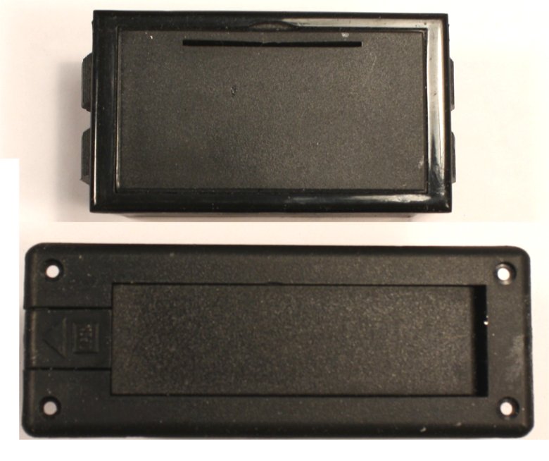
I have found that it's easier to remove the battery from the horizontal mount,
but it takes more horizontal real estate in the enclosure than the vertical
mount. Vertical won
here, because I wanted to leave as much room as possible for the PC board.
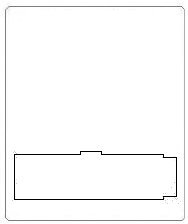
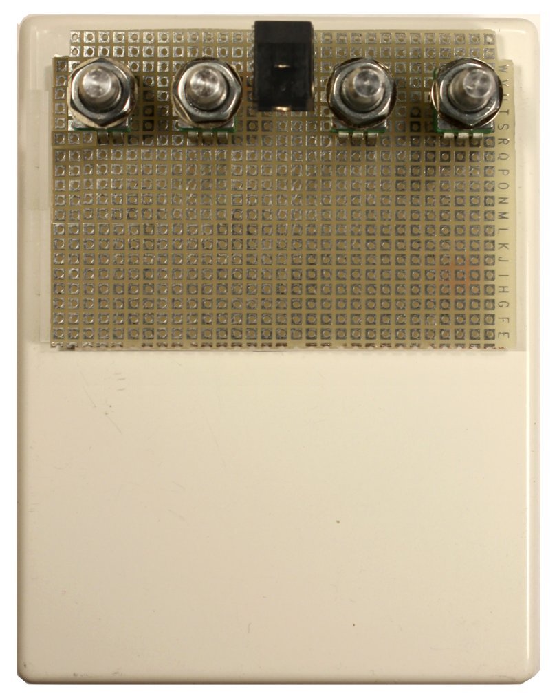
The next step was locating the position of the battery drawer on the
bottom plate of the enclosure and adding its outline to a paper drilling template.
Creating A Paper TemplateThis is a basic skill for being
able to roll-your-own enclosure designs. If you do not already know how to use
the basic functions of a drawing program like MS Paint (free in Windows
Accessories), Corel Draw or Jasc Paint Shop, this is the time to learn. For
purposes of laying out enclosures, you need to learn how to create and edit a simple, actual-size line
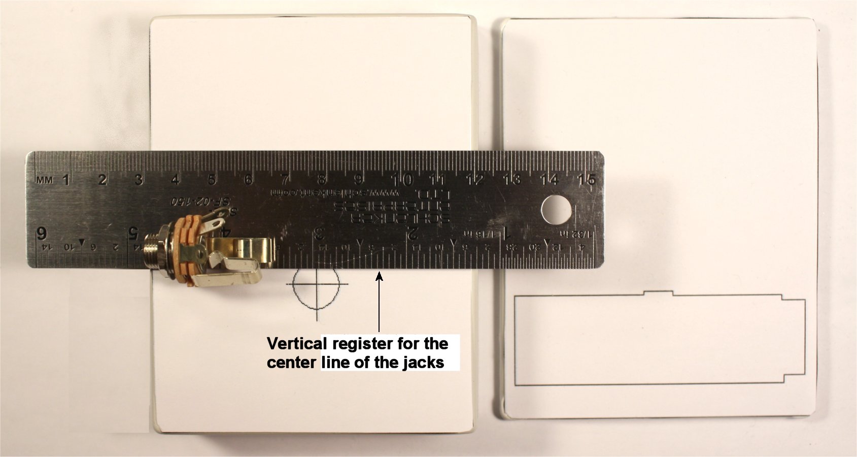
drawing, annotate it with labels and save it as a jpg file. I already had saved blank outlines for the
cover, base and sides of enclosures of various sizes, like these:
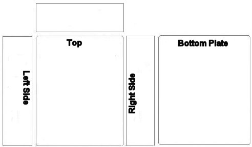
as well as hole outlines of various diameters for standard pots, jacks and
switches.
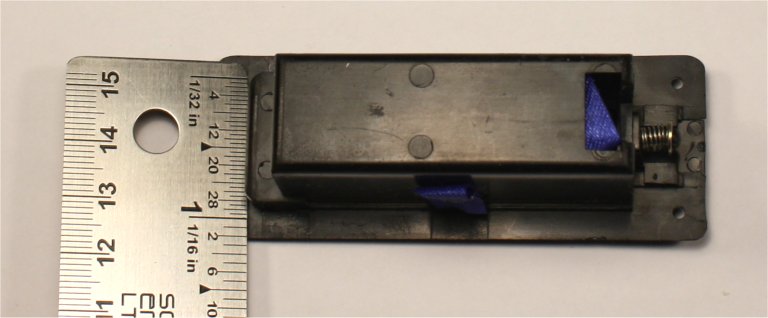
I took
measurements of the bottom of the battery drawer and
drew, within the outline for the bottom plate, an outline of the irregular
rectangular cutout that would be needed to accommodate it. It took a few iterations of correct-and-print to get a
result that matched the actual part and was properly positioned.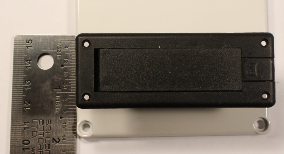
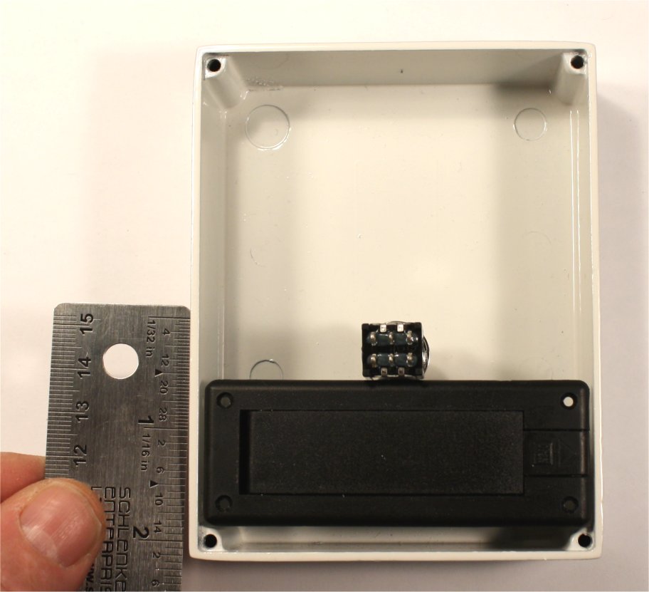
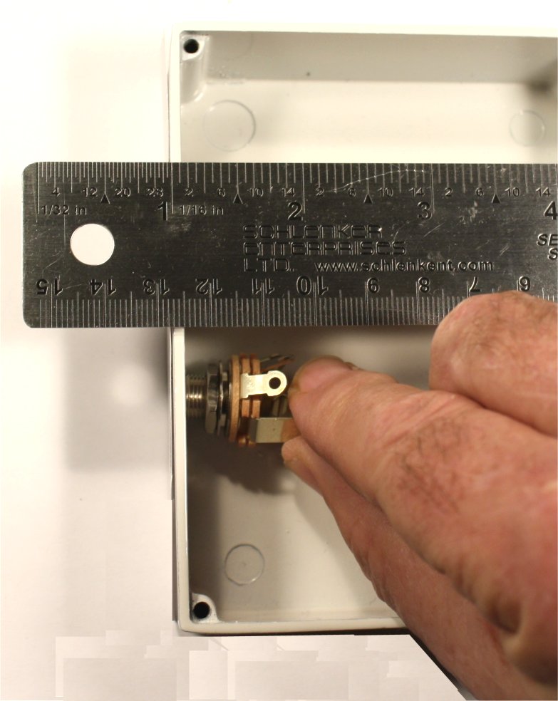
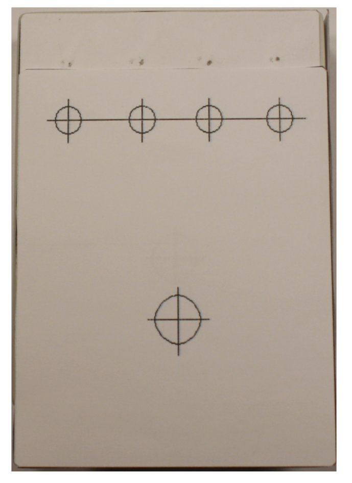
Knowing where the battery drawer would sit inside the enclosure, the next
logical step was locating the stomp switch directly north of it. I
took measurements again and created a 1/2" diameter hole on the center line of
the template for the face. Then I printed a copy of the template for the bottom plate and
taped it in place. This way, I could confirm the correct vertical position of the
switch hole by comparing its location with
the horizontal axis of the battery drawer.
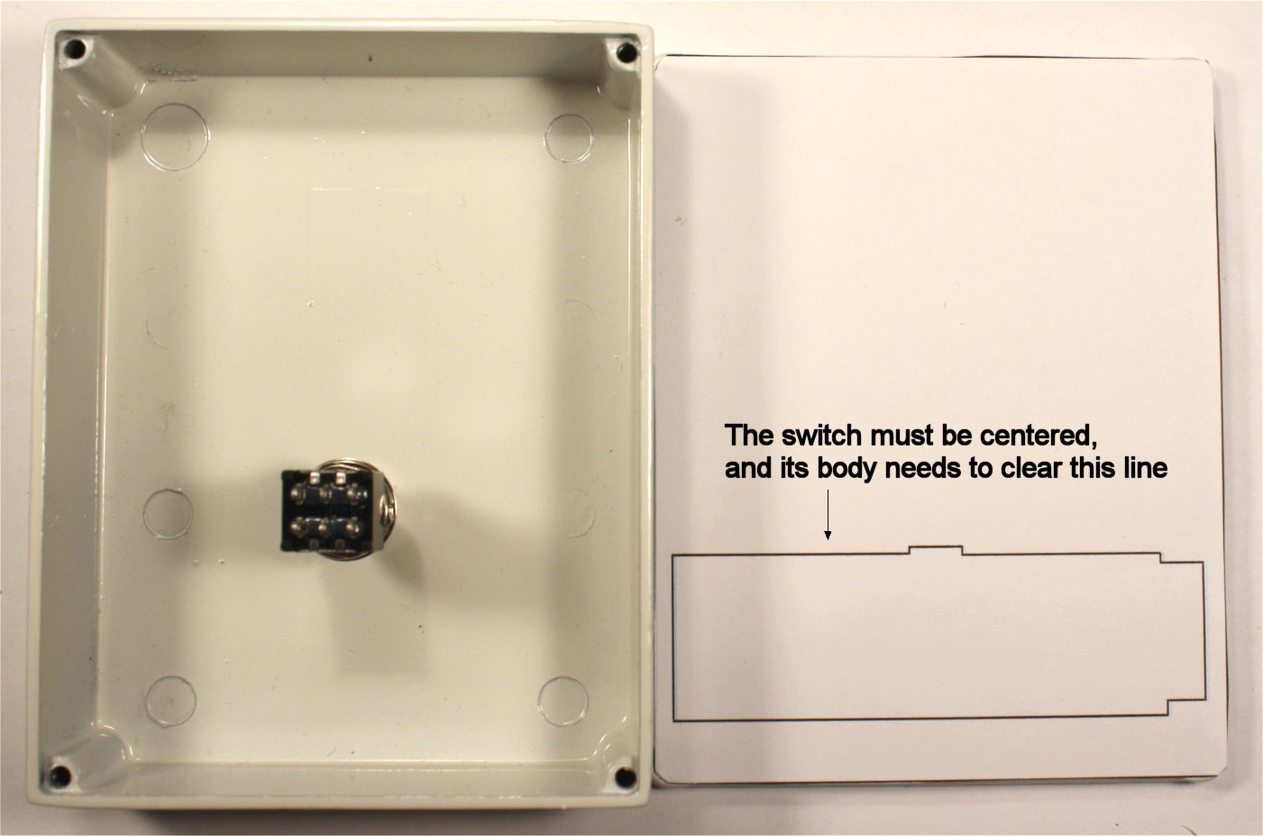
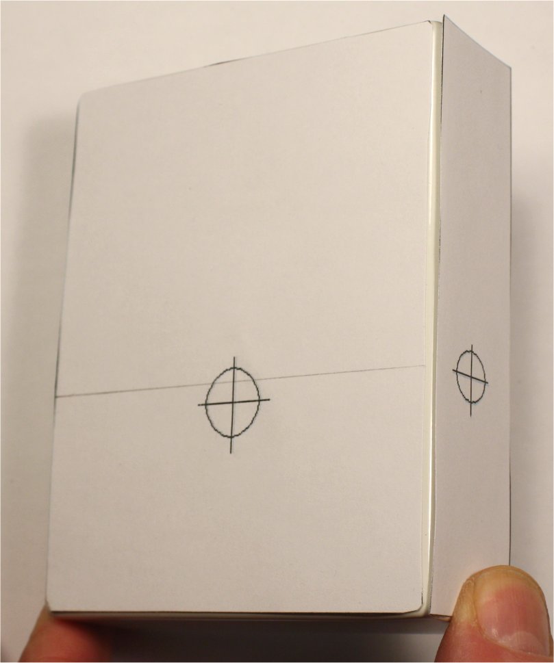
Now I did a test print of the outline of the face and adjusted the vertical
position of the outline for the switch hole. Once I was happy with that, I could locate the input and output jacks on
each side, just a little north of the switch so that they don't bump into the battery drawer,
either. I chose open-frame types for this build; if you are using board-mounted
or shrouded jacks, the layout considerations will be different.
I pencilled across the jack center line on top before cutting
out the outlines for the side panels and locating the holes for the input and
output jacks.
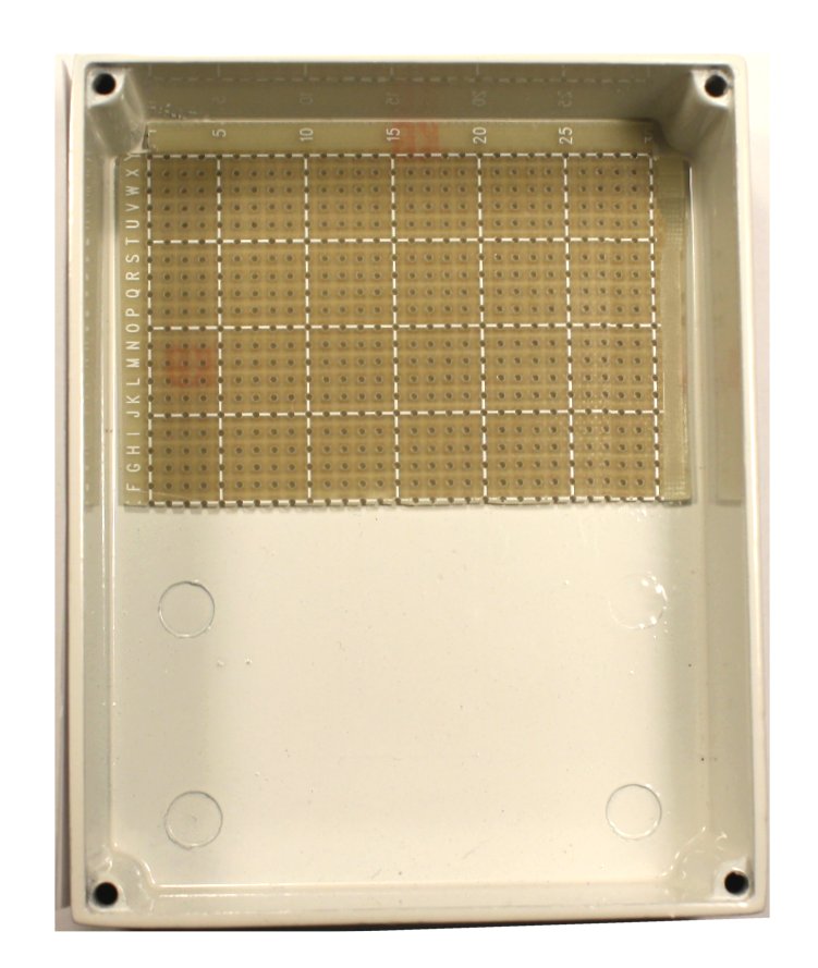
Now that I knew where the jacks would be, I could begin to
define the area that would be available for a board.
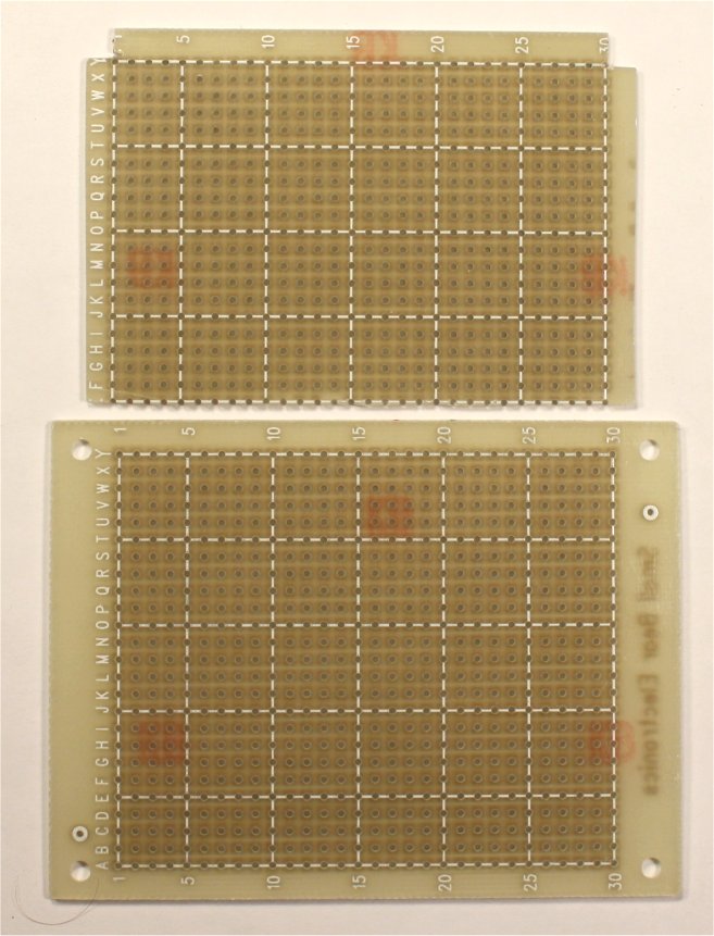
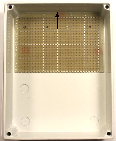
I took a few measurements, then cut a piece of perfboard down to
size. I did this now, because the precisely drilled (.100" center) holes in the board
would help define where the hole centers for the pots would be. Later, when I
design the PC board in EAGLE CAD, I will already know the board dimensions and
the number of holes that will be available for components.
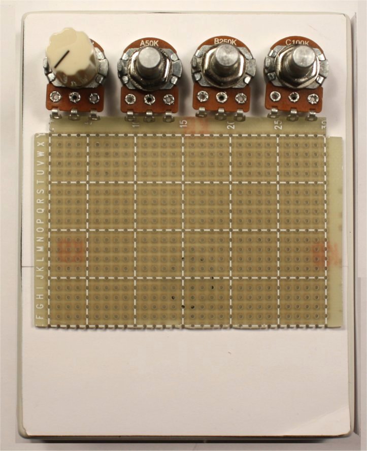
Remember I said that I knew that I would require four pots,
but I was not sure what size? So I lined up 16mm pots on top, and it was pretty
clear that they would leave me little flexibility for picking knobs. Also, I expect
to put a power jack up top, and I figured that the large cans would get in the
way.
I chose 9mm pots for this layout, PC-mount right-angle for ease of assembly.
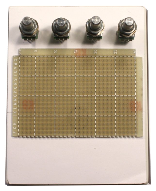
Now...how to locate the hole centers for the pots. The grid of
the board helps with working this out. Knowing that PC-mount pots will be
mounted on the solder side of the board, I set them in place temporarily and
experimented to find a vertical register that I was happy with. The precise
registration of the holes made it simple to position the pots. I made a choice
here to leave extra space in the middle between the two left-side and right-side
controls rather than spacing all evenly, because I decided that I wanted a board
mounted DC power jack. This arrangement will leave room for its footprint.
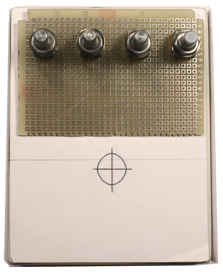
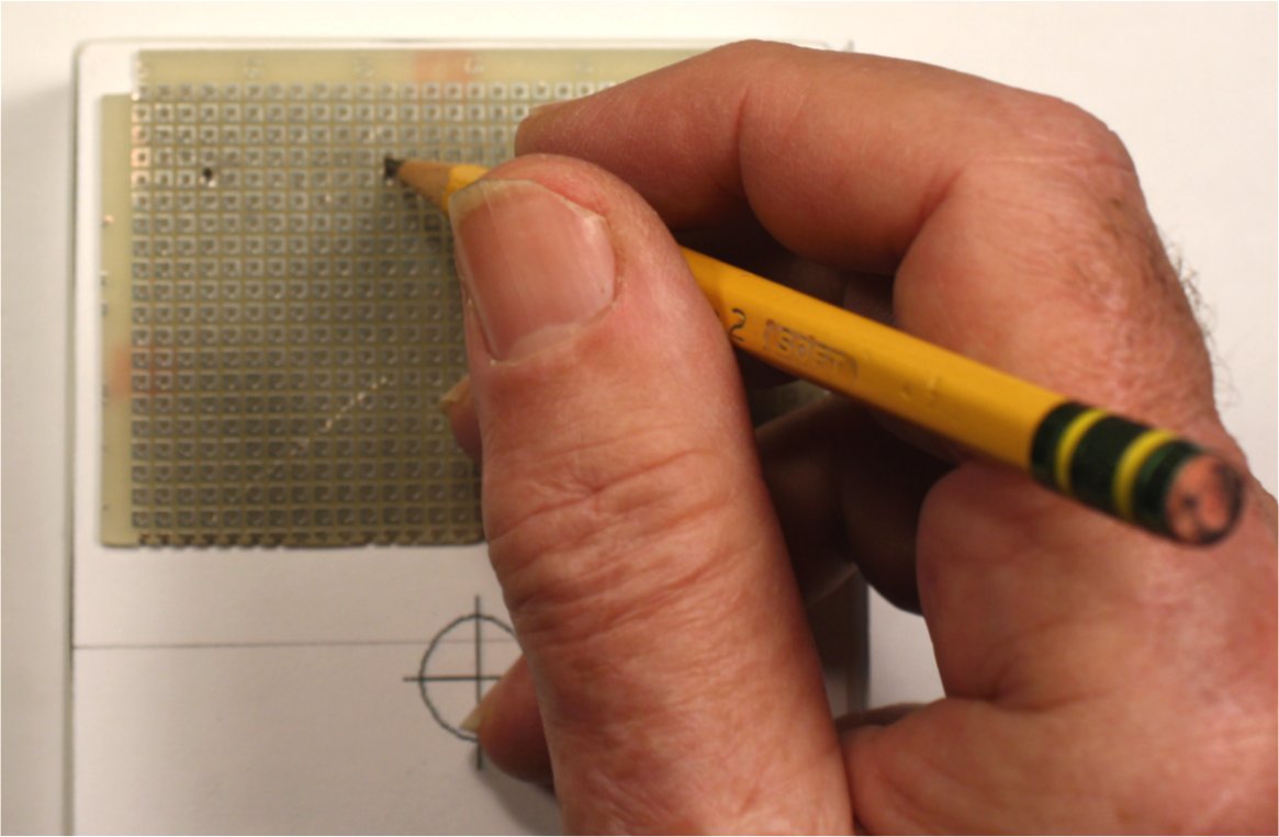
To locate the center of each pot, I turned the board over and
marked with a Sharpie.
This process gave me a "template" that I could lay down on the cover. I
marked each center point by poking a very sharp pencil through its hole. Then I
went back to my drawing program, added the hole outlines for the pots and went through
the "correct location-and-print" a few times. I found that I did not need to try a
"see-through"; cutting the new template to exact size and lining up horizontal
and vertical axes worked fine.
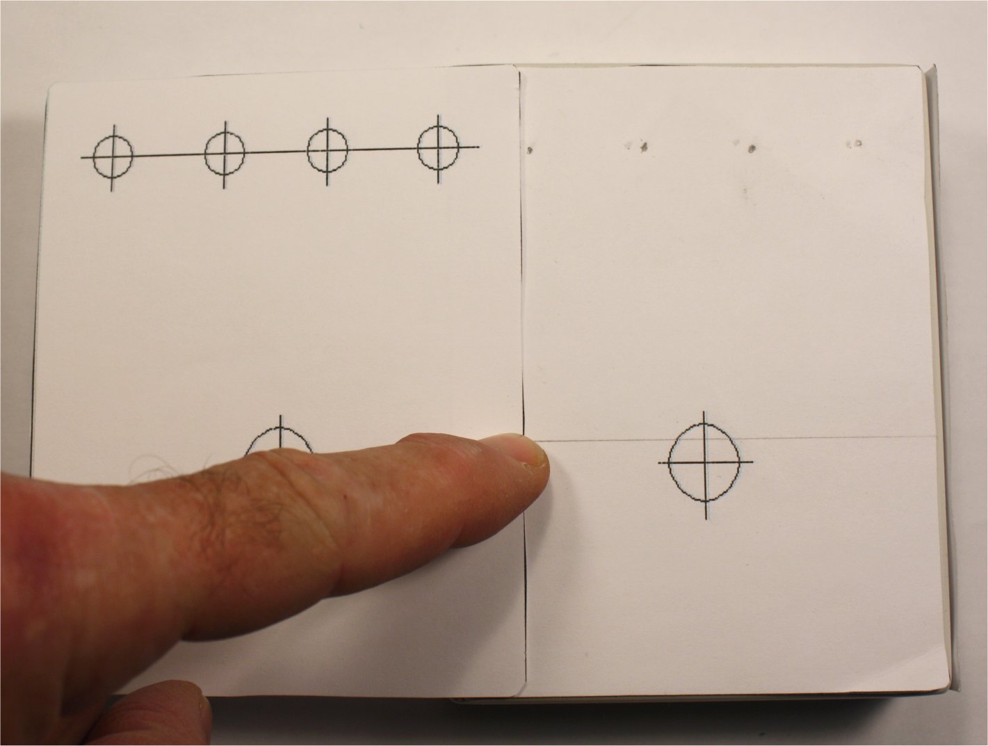
I added a hole for an in-use
LED mid-way between the stomp switch and the pots, and the top template is
complete. The location of this hole may change depending on where the LED driver
circuit winds up on the board design.
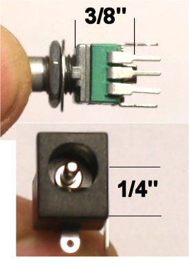
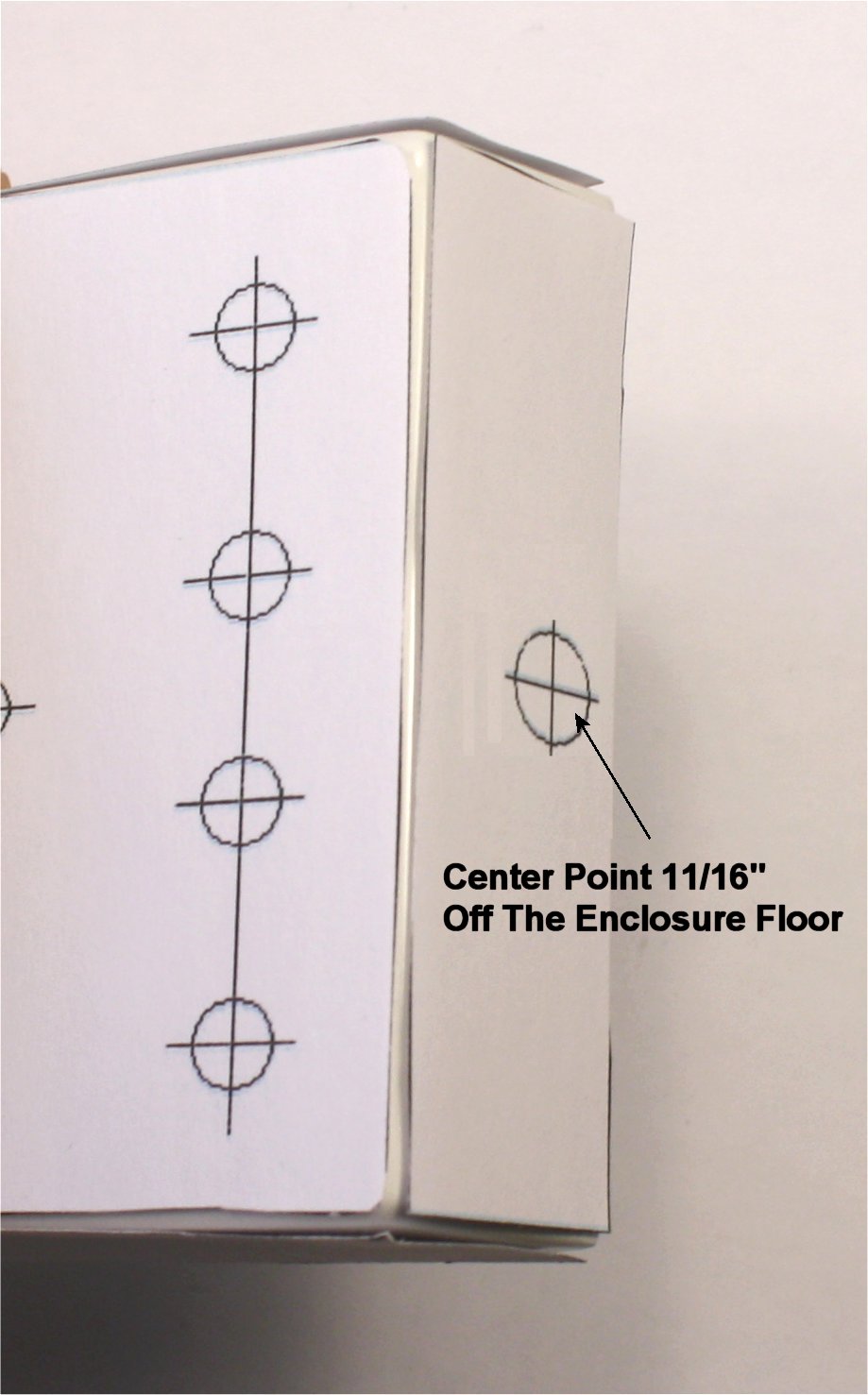
The last addition is a hole for the DC power jack on the top end
panel. The
diameter of the hole and the height of its center point will depend on the style
of jack. I decided to do PC-mount on-board; that will dictate a 5/16" hole
to allow a barrel plug to fit past the enclosure wall. Working out the height of
the center point from the enclosure bottom took a little figuring: The underside
of the board will sit on the pins of the pots, which are 3/8" from the face. The
thickness of the board itself adds 1/16" of height, and the height of the center
pin of the jack another 1/4"--total 11/16".
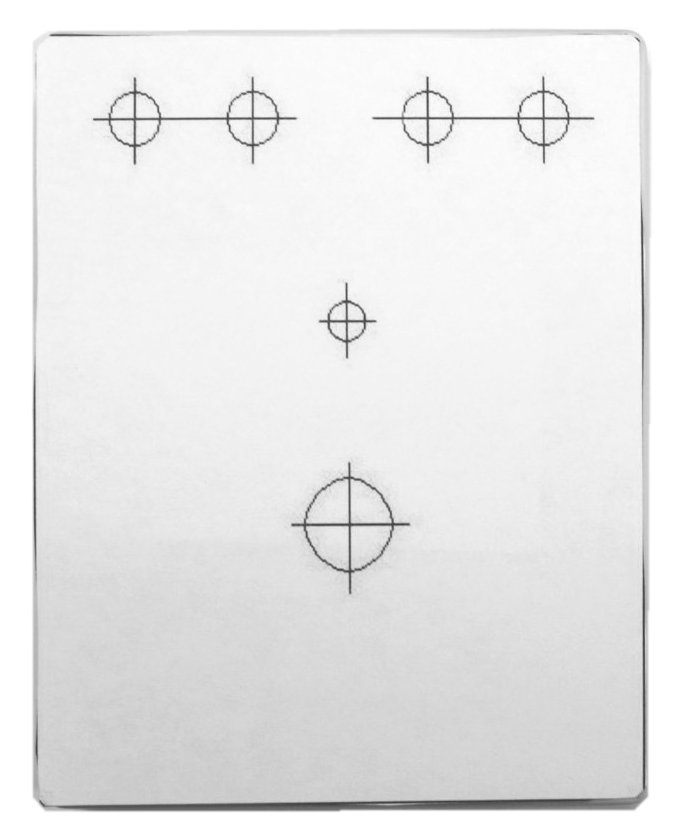
The result of this process was a complete set of drilling templates for a
four-knob "shell" based on a "BB"-size enclosure.
I hope you find these ideas useful in planning your own enclosure designs.
Comments and suggestions are welcome at smallbearelec@ix.netcom.com.