The IdeaBox and The IdeaBoard

© 2014 By Small Bear Electronics LLC

A typical solderless breadboard
 

is a bare-minimum essential tool for prototyping just about anything electronic. It works fine for effects, as well, until the builder wants to take what he has created on the bench and try it out on stage or in the studio...Even presuming that controls hanging in the air don't come loose, where do you mount a stomp switch, and how do you protect your magnum opus from always-mobile feet and hands?
 
A number of designers have created solderless prototyping "environments" specifically geared for effects development. Typically, they marry one or more breadboard "strips"


with a metal enclosure that can support controls and switching. Some of the ones I have seen are very good, but kind of expensive, I think because the designers put a lot of money into getting many pieces of their products made-to-order. With some thought, and "A Little Help From My Friends" at diystompboxes.com, the IdeaBox emerged as my take on this kind of prototyping tool.


Because I used a standard, off-the-shelf enclosure, the only things I had to have made were the brackets for supporting the controls and stomp switch. Those are available from my Stock List, SKU 2700G and 2700H respectively. The design allows for secure mounting of up to five pots, whose shafts poke through holes drilled in the cover of the box. Any desired variety of jacks can be mounted on the side walls. By mounting off-board items in this manner, the breadboard strips can remain right-side up, and mechanical stability in a gigging environment is assured.
 
It's so easy to put together and inexpensive that it's almost scary. I chose a New Sensor 1790NS and the bracket is sized accordingly, but clearly the concept can be made to work with any similar enclosure. Here is how to get the result shown above.
 
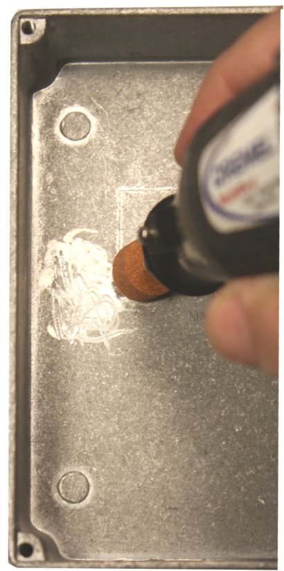
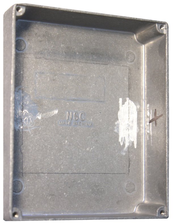
  1. To give the breadboard strips a completely flat purchase, use a grinding stone in a Dremel handpiece on any molding artifacts.

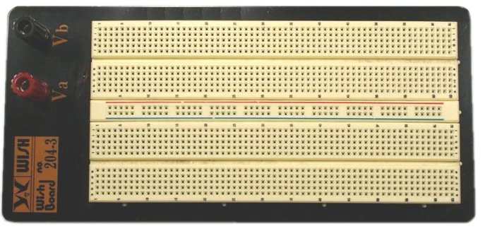
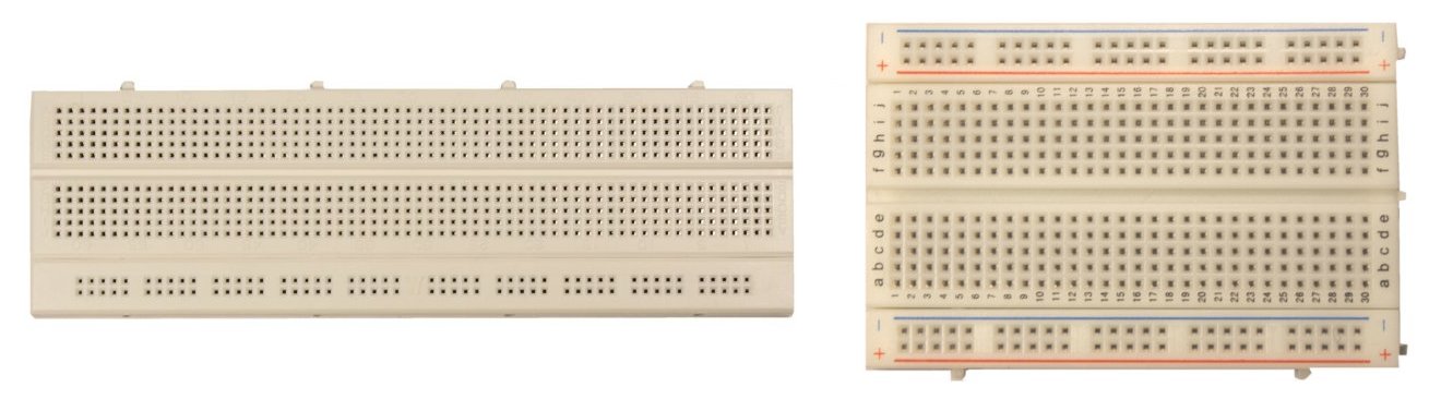
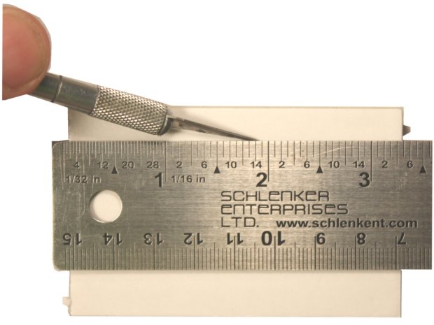
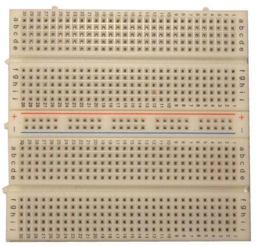
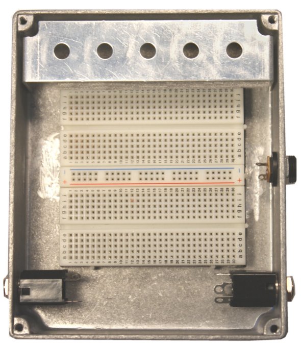
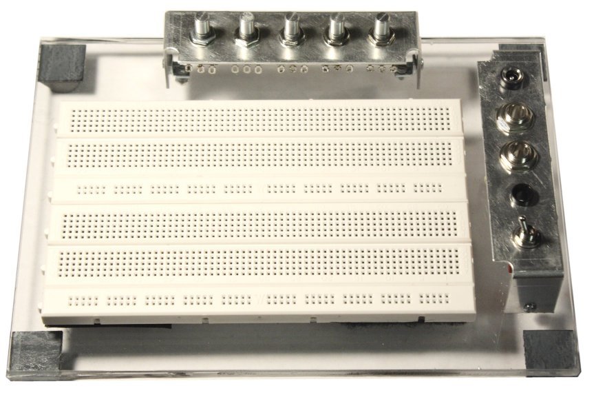
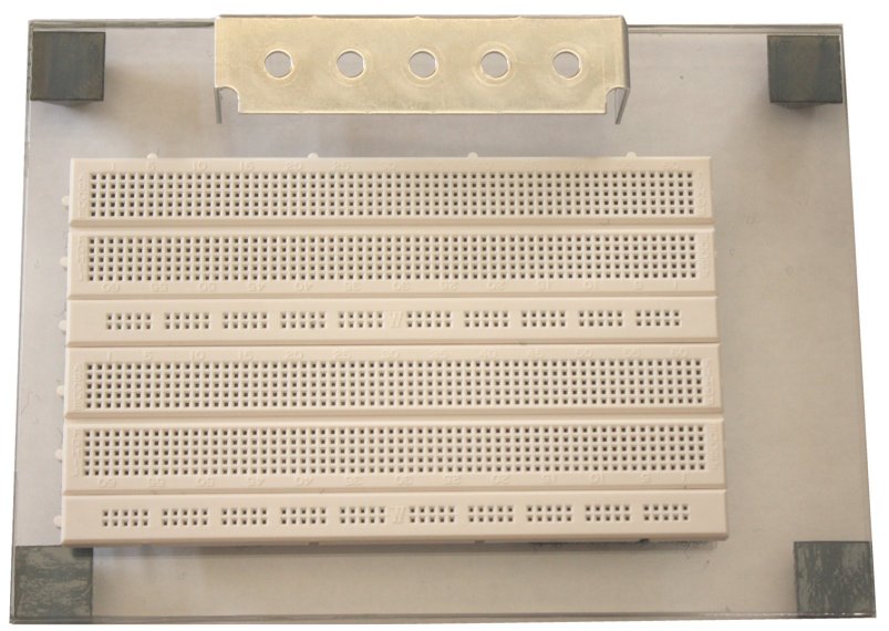
    Now figure out how many strips you want in the breadboard array and set it up. This style of small strip typically comes with two power busses. I decided to eliminate one power bus and share the remaining one between two component strips. If you follow suit, score the self-adhesive backing before breaking off the power bus and reassembling.

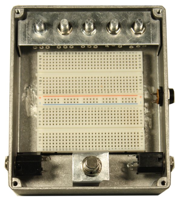
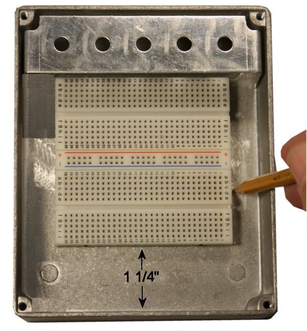
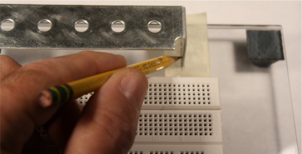
  2. Don't stick anything down yet. Put the potentiometer bracket in position and follow with the breadboard array. Outline in pencil the area where the array will sit. I elected to leave about 1 1/4" at the bottom where the switch will go. I figured to locate the power jack right next to the end of the power bus, so I marked the rough location on the side wall.

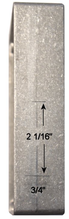
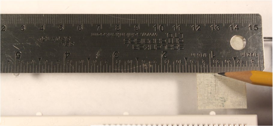
  3. On the right-side panel, I drew a line 3/4" up from the bottom to set the level of the center line of the power and input jacks. The center points of the holes can be eyeballed, or the pic shows the measurements that I used. Make a similar line on the left-side panel and locate the hole center for the output jack. Drill these three holes and then mock-up to make sure all pieces fit where they should. NB: If you want to be able to include a battery, there actually is room for one on the right side above the output jack. In that case, use a switching-type jack for power.

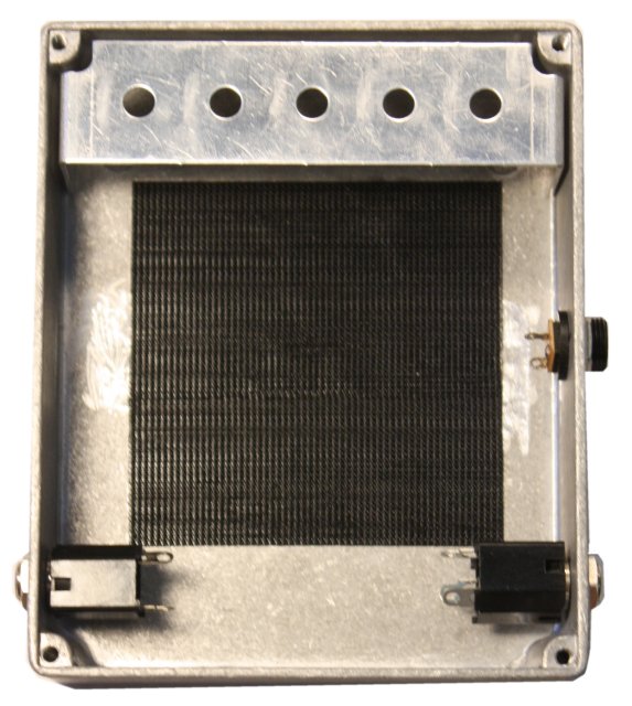
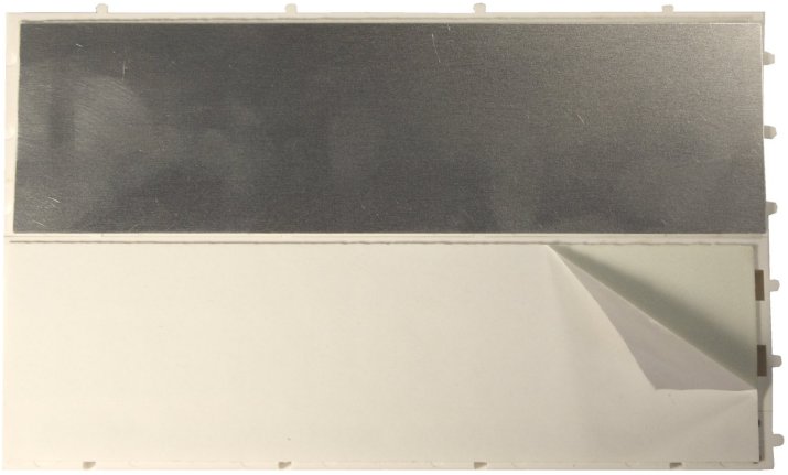
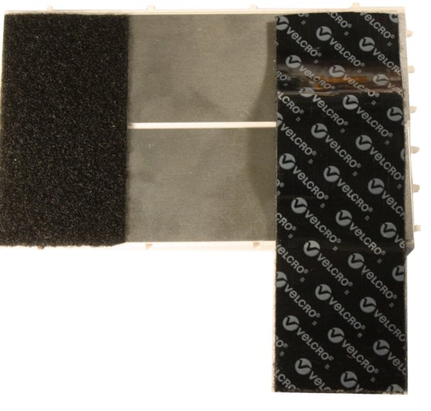
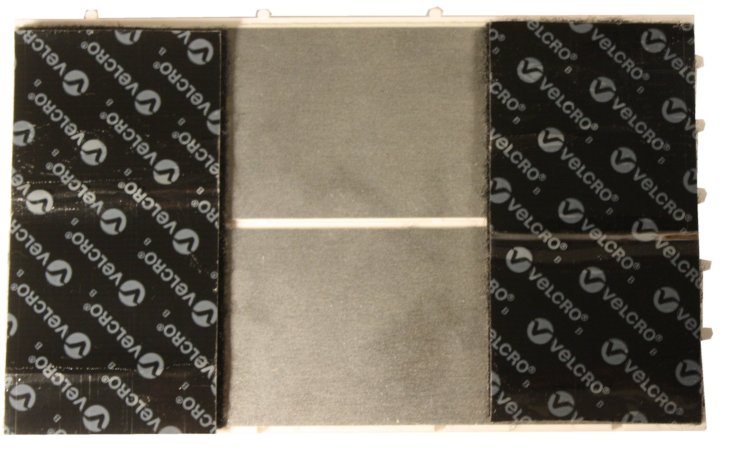
    Now I cleaned with Acetone the area in the enclosure where the breadboard array sits and laid down hard-side ("hook") Velcro material. Soft-side ("loop") material can now be applied to the breadboard array. Remember to remove the protective backing from the adhesive on the breadboard strips.

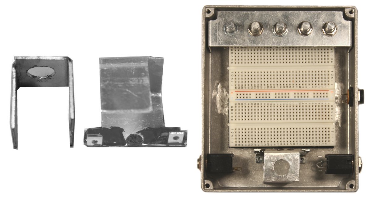
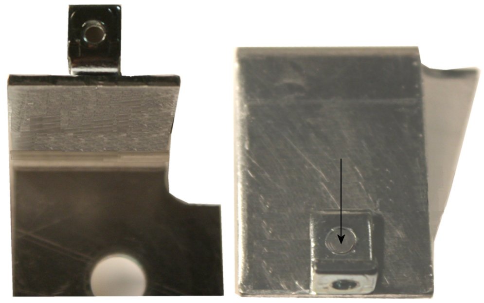
  4. If the cover is to simply come right down over the pots and switch, the switch needs a bracket, too. It's not absolutely necessary if you are willing to do a little wiggling at assembly. However, I hacked and hammered a pot bracket into something that works to show what's possible 
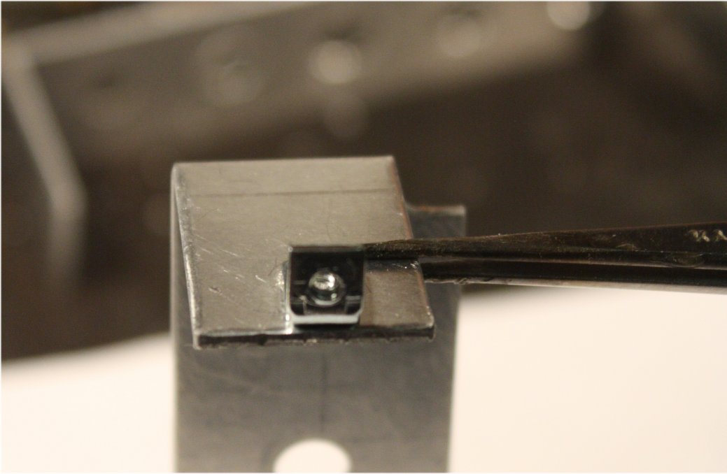
(also to have a prototype for manufacture!). To hold this cobbled bracket securely in position, I used J-B Weld to fasten a couple of small angle-brackets to the sides. That made it possible to drill mounting holes and insert screws from the bottom. The manufactured switch bracket can be ordered as SKU 2700H.

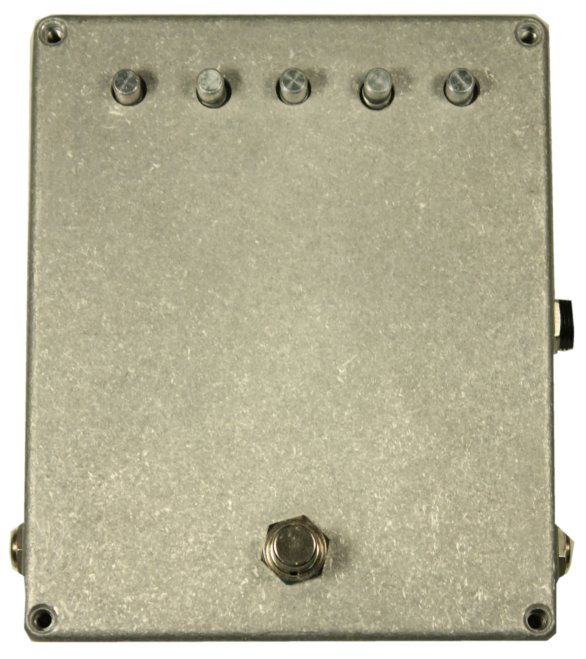
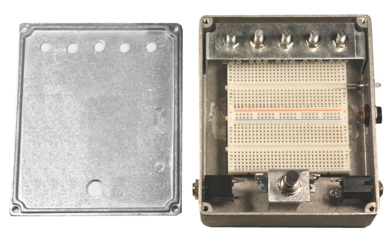
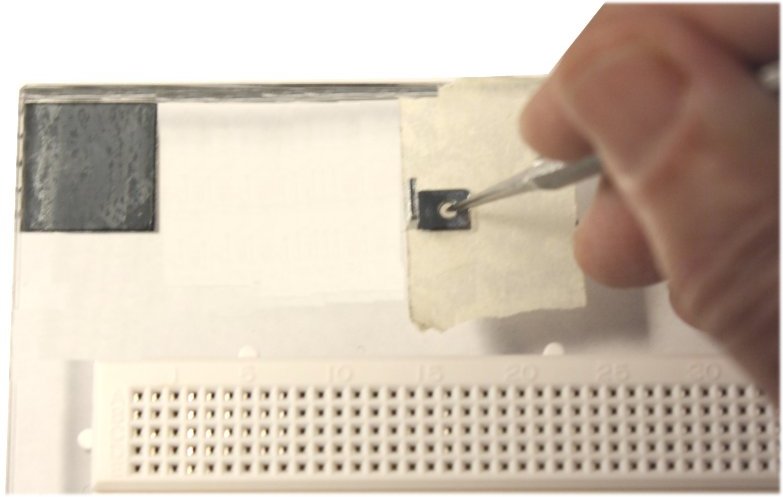
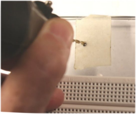
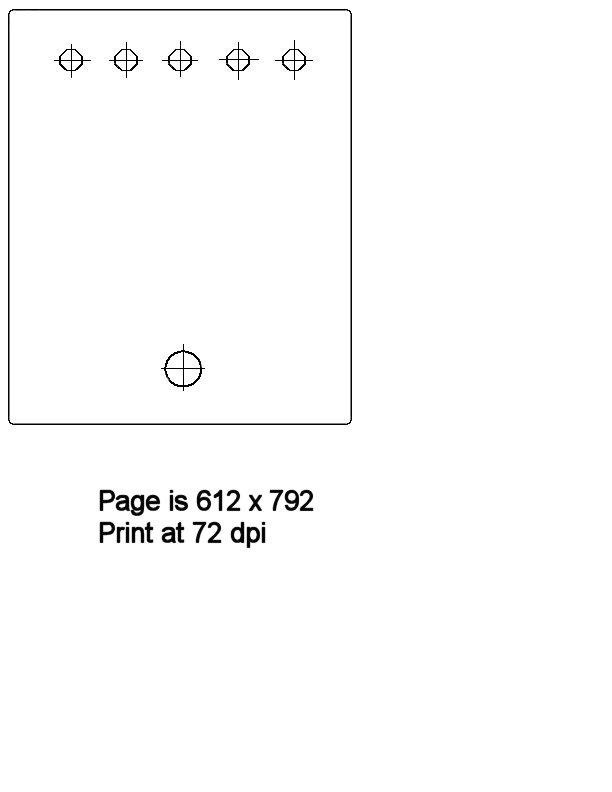
  5. Before tricking it out with wiring and doing possible mods, the cover plate needs to be drilled for the pot shafts and the stomper. A drilling template can be downloaded from here. Cut to size, tape to the cover with double-stick tape and drill. Install pots in the bracket and slip the drilled cover over all. Everything line up? Add rubber feet and it's Ready To Rock!

  6. This is a generic setup that I think will work for most people. But it's missing an in-use LED. I can think of a couple of ways to accommodate one, and you might want to think about the method in case you need to do more tooling.
  • You can have an LED stick up from the breadboard array and poke into a lens or bezel mounted on the cover.
  • You can mount an LED on the pot bracket and wire it to stomper and power.
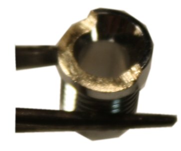
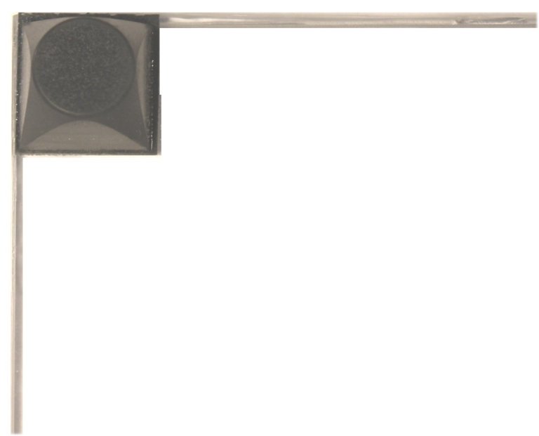
  • I have seen LED mounts that are designed to mount on an outside panel with the LED facing upward, or it is possible to hack a standard bezel so that more of an LED is viewable from the side. The pics show the idea. I cut off half of the top a 5mm bezel. If you use a cutoff wheel for this job WEAR GOGGLES! I needed a high-brightness LED scuffed up with Carborundum paper to diffuse its output. I got workable brightness with a 6.8K series resistor at 9 Volts...YMMV. The bezel and LED can be mounted wherever you like on the side walls, and the usual drop of Krazy Glue to secure the LED in the bezel is fine.

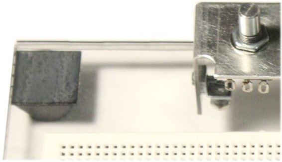
The stomper shown is the Alpha long-bushing 3PDT SKU 0200D5. It puts more thread for a nut outside the enclosure.

I also wanted to mention an idea from a customer (Thanks, Murad!) regarding the mounting of the pots. If you use a cutoff wheel or nibbling tool to open up the holes in the bracket so that they become slots, pots can slide in and out--very convenient! An issue that I saw is that making those cuts made the bracket much less rigid. I compensated by using epoxy glue to marry the bracket to the enclosure.

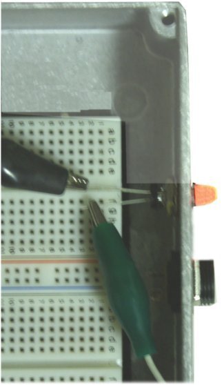
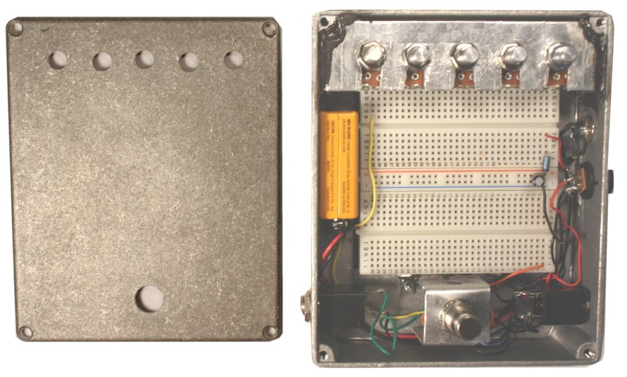
Here is a completely tricked-out box, ready for work. The wiring is standard, just as you would wire a pedal. I presumed that any first stage would begin at the upper left and complex builds would end at the lower right, but your needs will dictate the layout.

The "IdeaBoard"
 
While I was working out the design of the bracket, it occurred to me that it could also be the linchpin of an economical, desktop, "deluxe breadboard" specifically geared for effects work. Commercial versions of these exist, of course, but they are uniformly expensive and aren't set up for the typical inputs and outputs of a pedal. Happily, I found that the hole-spacing that I had planned for the pots will also permit mounting jacks and switches.
 

I am sure that some builders will have different visions. However, here is a step-by-step guide to creating what is shown in the above pic.


  1. For the base, I used a piece of 1/4"-thick Lucite cut 6 1/2 inches by 9 inches. You can order this from my Stock List as my SKU 2700I, or you can ask at a local plastic supplier to see if they have a scrap that they'll cut to size for you. The unfinished edges will be rough, so you may want to sand them with 220-grit sandpaper. Wood is also fine if you are on a tight budget.
  2. Lucite will come covered with a protective film. Cover your work area with a towel or soft cloth, and then remove the film. Attach a rubber foot in each corner. I used 3M #SJ-5514, my SKU 0320.


  3. Snap the breadboard strips together and prepare them for mounting. The Wish strips that I used (SKU 2700B) have a self-adhesive back and come with a metal bottom plate for shielding. Remove the protective backing from the adhesive and very carefully lay the bottom plates in place on each surface.

  4. I wanted the strips to be removable from the base for convenience and flexibility, so I arranged to hold them down with pieces of 2-inch wide Velcro. I cut a piece of the soft ("loop") material exactly as long as the left edge and stuck this in place. Then I did the same on the right side. To ensure that the "pads" would occupy the same area on the Lucite base, I laid the hard ("hook") material down on the right-hand soft side and cut to length. Then I did the same on the left side. Clearly, your method and materials may vary here.

  5. I did the this build entirely by eyeball, depending on the precisely cut base, bracket and breadboard strips for lining things up parallel. If you are uncomfortable with that, you may want to lay down strips of masking tape as guides. I laid the bracket down first and nudged it parallel with the top edge of the base. Then I removed the backing material from the Velcro, turned the assembly over and Very Carefully lowered it into place, parallel with the bottom edge of the base.

  6. Figure out where you want the left edge of the bracket to sit. In mine, it is about 2 1/8" from the left edge of the base. Lay down a piece of masking tape to mark where you want the edge of the bracket, lining up the tape parallel with the left edge of the base. Now lay a small right-angle bracket (SKU 8010) precisely on the edge of the tape. Pick up the large bracket without disturbing the position of the small one, and mark the exact center of the mounting hole with a scribe or scratch awl.

  7. I have found that I can drill Lucite without cracking it using ordinary HSS (high-speed steel) twist drills, as long as the area where I'm drilling is covered with masking tape. The mounting hole is 1/8" diameter.

  8. The next step is locating and drilling a mounting hole on the side flap of the bracket. Use soldering tweezers to hold a small bracket centered on the outside of the flap with its bottom surface exactly level with the bottom edge of the large bracket. The pics below show this from several views. Scribe the center of the mounting hole of the bracket and drill a 1/8" hole at that point in the flap.

  9. With a 4-40 screw, screw the small bracket down to the base and secure below with a nut and compression lockwasher. Line up this bracket parallel with the left edge of the base and screw the large bracket in place on the left side. I got impatient and wanted to see what the pots would look like when installed, but you get the idea.

  10. Line up the bracket precisely parallel with the breadboard strips and lay down a strip of masking tape under its right edge. On the inside edge of the bracket, pencil a line on the tape. Unscrew the left-hand brackets and lay a straightedge through the center of the mounting hole. Line up the straightedge parallel with the breadboard strip and mark on the right side where the straightedge intersects the pencil line. Now you have the point for drilling the hole for the right-hand small bracket. Drill that hole and install a small bracket. On the right side of the large bracket, repeat the procedure for creating a mounting hole. Secure the large bracket on both sides.

  11. The bracket for the pots is done. The procedure for mounting the bracket for jacks is exactly the same. When you have it mounted, figure out which jacks you want where and ream out holes accordingly.

A customer asked what jacks, etc. I used in the pic above. For input and output, Switchcraft #11, my SKU 0600; for DC power, an unswitched 2.1mm jack SKU 0611G. Then choose an LED Bezel of the size you want and a toggle switch for bypass. I used a 3PDT, SKU 0221A.

The exact wiring will depend on your layout of jacks, switch and LED, but the idea is the same as what I show for the IdeaBox. I hope you find these tools as useful as I have. Comments and suggestions are welcome at smallbearelec@ix.netcom.com.